Flow guiding device for heat pump drying box

A technology of diversion device and drying box, which is applied in the direction of drying, drying machine, drying gas arrangement, etc., which can solve the problems of low drying efficiency, inability to ensure uniform drying of crops, and accumulation of cold air, so as to ensure the drying The effect of dry efficiency

Pending Publication Date: 2017-06-20
HUNAN XIAWEIQI DOMESTIC FUNGUS DEV CO LTD
View PDF10 Cites 5 Cited by
  • Summary
  • Abstract
  • Description
  • Claims
  • Application Information

AI Technical Summary

Problems solved by technology

The system simply divides the main body of the drying room into a return air channel and a drying area. This simple separation will lead to uneven distribution of hot air in the drying room, which cannot ensure that the crops can be dried evenly; and the The hot air flow of the drying system is in the way of bottom in and top out, which can easily cause cold air to gather under the drying area, resulting in low drying efficiency

Method used


Image

  • Flow guiding device for heat pump drying box
  • Flow guiding device for heat pump drying box
  • Flow guiding device for heat pump drying box

Examples


Embodiment 1

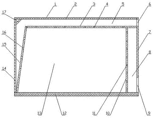
[0032] Referring to the accompanying drawings: in order to solve the above problems, the technical solution adopted in the present invention is: a flow guiding device for a heat pump drying box, including a drying box 1,

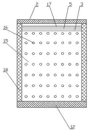
[0033] The upper and lower parts of the front wall 7 of the drying box 1 are respectively provided with an air inlet 6 and an air outlet 9, and the rear deflector 15 and the upper deflector 3 are respectively installed on the inner rear side and the upper side of the drying box 1. , the upper deflector 3 is located below the air inlet 6; the rear deflector 15 and the upper deflector 3 divide the drying box 1 into an air inlet channel 8 and a drying area 13, and the rear deflector 15 and / or the upper deflector 3 is provided with an air outlet; the air outlet includes the air leakage hole 4 and the drainage hole 16 respectively arranged on the upper deflector 3 and the rear deflector 15 .

[0034] The front side of the drying box 1 is also provided with a fron...

Embodiment 2

[0043] Compared with Embodiment 1, the flow guiding device for the heat pump drying box 1 of this embodiment has the following differences:

[0044] The upper deflector 3 is connected between the side walls 18 on both sides of the drying box 1 in such a way that the front end is inclined downward, the angle between the upper deflector 3 and the horizontal plane is 2°, and the vent hole 4 The total area of ​​the upper deflector is 5% of the area of ​​the upper deflector 3, and the longitudinal distance and the transverse distance between the adjacent said vent holes 4 are respectively 5% of the length and width of the upper deflector 3; Installation is carried out in a downwardly inclined manner, so that the hot air flow can flow to the rear deflector 15 more smoothly, avoiding the excessive pressure of the hot air flow in the air inlet channel 5 of the upper deflector 3 section, and keeping the total area of ​​the vent hole 4 unchanged Under certain circumstances, increasing t...

Embodiment 3

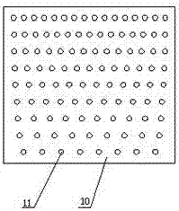
[0048] Compared with Embodiment 1, the deflector for the heat pump drying box 1 of this embodiment has the following differences: In this embodiment, a rear deflector 10 and an upper deflector are respectively installed on the rear side and the upper side of the drying box. Deflector 3, instead of a front deflector, the rear deflector 10 and the upper deflector 3 divide the drying box into an air inlet channel 5 and a drying area 13,

[0049] Specifically, the hot air enters the air inlet channel 5 from the air inlet 6, and when the hot air flows through the air inlet channel 5 of the upper deflector 3 section, due to the high wind pressure, part of the hot air will flow into the oven from the vent hole 4 of the upper deflector 3. Dry area 13; when the hot air enters the air inlet channel 5 of the rear deflector 15, it will flow into the drying area 13 from the drainage holes 16 on the rear deflector 15; the hot air after drying the materials in the drying area 13 Directly flo...


PUM


Abstract

The invention provides a flow guiding device for a heat pump drying box. The flow guiding device comprises the drying box as well as a front flow guiding plate, a back flow guiding plate and an upper flow guiding plate which are arranged inside the drying box; an air inlet and an air outlet are formed in the upper part and the lower part of the front wall of the drying box respectively; the back flow guiding plate and the upper flow guiding plate are mounted on the back side and the upper side of the inside of the drying box respectively; the upper flow guiding plate is located below the air inlet; the drying box is separated into an air inlet channel and a drying area by the back flow guiding plate and the upper flow guiding plate; and air outlet holes are formed in the back flow guiding plate and/or the upper flow guiding plate. By the aid of the flow guiding device, hot air in the drying box can be uniformly distributed, the drying uniformity of the drying box for a to-be-dried material can be guaranteed, the drying efficiency of the drying box can be improved, and the energy consumption can be reduced.

Description

technical field [0001] The invention relates to the technical field of drying treatment, in particular to a flow guiding device for a heat pump drying box. Background technique [0002] With the development of agricultural production and industrialization equipment, indoor drying technology has become an indispensable means to promote the process of agricultural industrialization. In traditional agricultural production, when drying crops such as medicinal materials, rice, vegetables, and fungi, drying, electric heating, or gas heating are often used. These traditional drying methods not only have a long drying cycle and are easy to cause Deterioration of crops due to under-drying or over-drying. [0003] CN203561172U discloses an air source heat pump drying system, comprising a main body of a drying room, a heat pump, an internal circulation fan, and a dehumidification fan. Controller control. The system simply divides the main body of the drying room into a return air ch...

Claims


Application Information

Patent Timeline
Patent Type & Authority Applications(China)
IPC IPC(8): F26B21/00
CPCF26B21/004
Inventor 夏义良
Owner HUNAN XIAWEIQI DOMESTIC FUNGUS DEV CO LTD
Why Eureka
Try Eureka