Bionic gas flow rate sensor of hair seam combination

A gas flow rate and sensor technology, applied in the direction of fluid velocity measurement, instrumentation, velocity/acceleration/impact measurement, etc., can solve the problems of being affected by temperature, expensive, and low precision of mechanical detection, and achieve good economy, simple structure, Ease of mass production

Active Publication Date: 2017-06-20
JILIN UNIV
View PDF8 Cites 22 Cited by
  • Summary
  • Abstract
  • Description
  • Claims
  • Application Information

AI Technical Summary

Problems solved by technology

However, at present, the above measurement methods have certain problems in practical application: low precision of mechanical detection, easy aging of equipment, and operation is affected by temperature, and the detection fluctuates greatly; the sensor chip must be electrically heated when the hot-wire hot-fi

Method used


Image

  • Bionic gas flow rate sensor of hair seam combination
  • Bionic gas flow rate sensor of hair seam combination
  • Bionic gas flow rate sensor of hair seam combination

Examples


Embodiment Construction

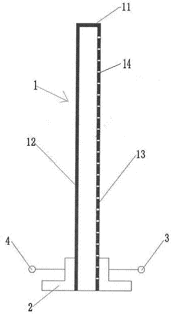
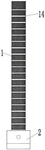
[0014] Such as figure 1 with figure 2 As shown, this embodiment is composed of a caulking rod 1, a fixed base 2, a first electrode lead 3 and a second electrode lead 4, and the caulking rod 1 is assembled with the fixed base 2 to form a cantilever beam structure; The side 12 leads out the first electrode lead 3, and the right side 13 points out the second electrode lead 4, the first electrode lead 3 and the second electrode lead 4 are all fixed on the fixed base 2, wherein the caulking hair rod 1 is insulated by elastic The upper surface 11, the left side 12 and the right side 13 of the caulking hair shaft 1 are all coated with a conductive material layer, and the conductive material layer on the right side 13 is processed with micro-nano slits 14 in the horizontal direction.

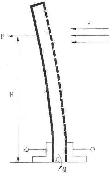
[0015] Working process and principle of the present invention:

[0016] Such as image 3 As shown, when the airflow with a velocity of V is tested, the force F exerted by the airflow on the caulking...


PUM


Abstract

The invention discloses a bionic gas flow rate sensor of hair seam combination. The sensor is formed by an embedded seam hair rod, a fixing pedestal, a first electrode lead wire and a second electrode lead wire. The embedded seam hair rod and the fixing pedestal are assembled into one body so as to form a cantilever beam structure. The first electrode lead wire is led out from a left side and the second electrode lead wire is led out from a right side. The first electrode lead wire and the second electrode lead wire are fixed to the fixing pedestal. The embedded seam hair rod is made of an elastic insulating material. An upper surface, the left side and the right side are coated with conductive material layers. A micro-nano seam is processed on the conductive material layer of the right side along a horizontal direction. When a gas with a slow flow rate flows through, a gas flow and the embedded seam hair rod are interacted so that the embedded seam hair rod generates a certain degree of deflection. When the micro-nano seam of the right side is stretched, a deflection angle is large, a seam width is increased and a resistance is large too. When the micro-nano seam is compressed, the deflection angle is large, the seam width is decreased and the resistance is small. Therefore, perception measurement of a gas flow rate is realized.

Description

technical field [0001] The invention belongs to the technical field of gas flow velocity measurement, and in particular relates to a gas flow velocity sensor. By detecting the resistance change in the circuit, the measured gas flow rate can be determined. Background technique [0002] It is of great significance to accurately measure gas micro-flow velocity. At present, the main gas flow velocity measurement methods include mechanical gas flow velocity measurement and detection, hot-wire hot film gas flow velocity detection (HWA), ultrasonic and laser Doppler (LDA) flow velocity detection methods, etc. However, at present, the above measurement methods have certain problems in practical application: low precision of mechanical detection, easy aging of equipment, and operation is affected by temperature, and the detection fluctuates greatly; the sensor chip must be electrically heated when the hot-wire hot-film gas flow rate is detected. The power consumed is large and it i...

Claims


Application Information

Patent Timeline
IPC IPC(8): G01P5/08
CPCG01P5/086
Inventor 张俊秋陈思琪陈道兵陈文娜宋洪烈刘林鹏张卡牛士超韩志武王慧远穆正知李博朱斌
Owner JILIN UNIV
Why Eureka
Try Eureka