Overtemperature protection circuit and driving method

An over-temperature protection circuit and circuit technology, applied in emergency protection circuit devices, circuit devices, emergency protection devices with automatic disconnection, etc., can solve problems such as abnormal state, passive device operation, device operating voltage and temperature drift, etc.

Active Publication Date: 2017-06-20
BOE TECH GRP CO LTD +1
View PDF5 Cites 0 Cited by
  • Summary
  • Abstract
  • Description
  • Claims
  • Application Information

AI Technical Summary

Problems solved by technology

[0002] For the continuous integration of functions of existing integrated circuits, the increase of circuit scale, the temperature rise caused by power consumption and the increase of ambient temperature will have an impact on the stability of circuit performance. In addition, for the existing integrated circuit chip IC, the internal Devices with integrated over-temperature protection (OTP) function are mostly activ

Method used


Image

  • Overtemperature protection circuit and driving method
  • Overtemperature protection circuit and driving method
  • Overtemperature protection circuit and driving method

Examples


Embodiment Construction

[0040] In order to make the objectives, technical solutions and advantages of the present invention clearer, the embodiments of the present invention will be described in detail below in conjunction with the accompanying drawings. It should be noted that the embodiments in the application and the features in the embodiments can be combined with each other arbitrarily if there is no conflict.

[0041] The steps shown in the flowchart of the drawings can be executed in a computer system such as a set of computer-executable instructions. Also, although a logical sequence is shown in the flowchart, in some cases, the steps shown or described may be performed in a different order than here.

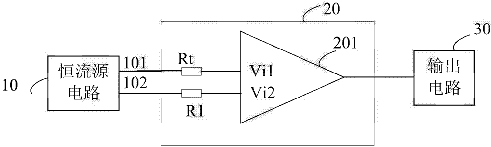
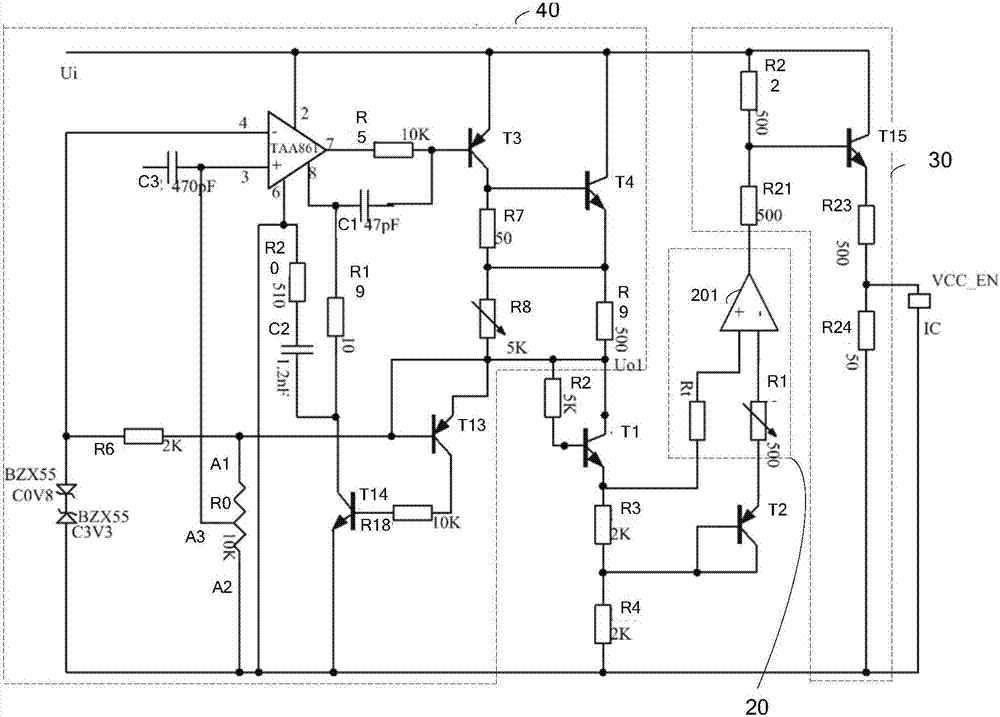
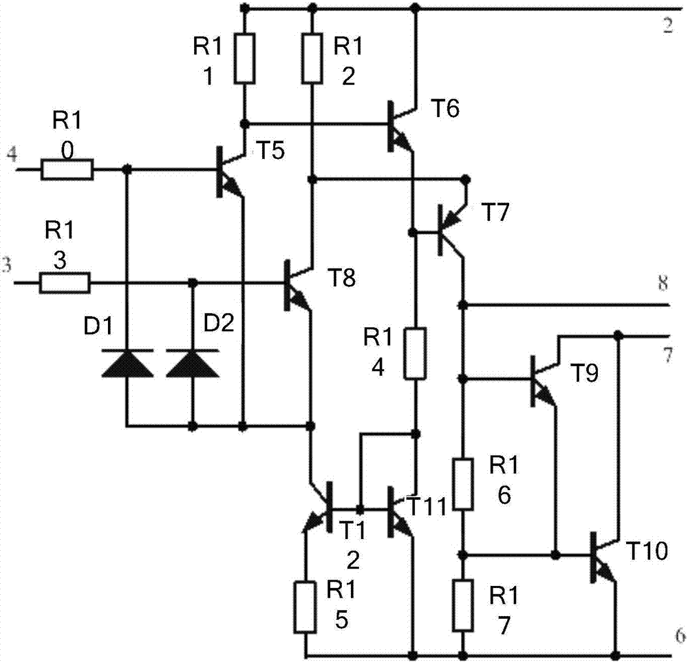
[0042] An embodiment of the present invention discloses an over-temperature protection circuit, which is composed of an operational amplifier and a transistor to form a constant current source, and a voltage comparator, an adjustable resistor, and a negative temperature coefficient thermistor form ...


PUM


Abstract

Embodiments of the invention disclose an overtemperature protection circuit and a driving method. The overtemperature protection circuit comprises a constant current source circuit, a comparator circuit and an output circuit, wherein the comparator circuit comprises a negative temperature coefficient resistor, a first resistor and a voltage comparator; the comparator circuit compares a first voltage end at the first input end and a second voltage value at the second input end, and outputs a control signal according to a comparison result, wherein when the temperature is greater than or equal to a protection threshold value, the control signal is an overtemperature control signal; and the output circuit is used for outputting a switch-off enabling signal when the comparator circuit outputs the overtemperature control signal. By virtue of the scheme provided by the embodiment, a device can be switched off in time at an overhigh temperature so as to protect the device.

Description

Technical field [0001] The invention relates to electronic circuit technology, in particular to an over-temperature protection circuit and a driving method. Background technique [0002] In view of the continuous integration of existing integrated circuit functions, the increase in circuit scale, the temperature rise caused by power consumption and the increase in ambient temperature will affect the stability of circuit performance. In addition, for the existing integrated circuit chip IC, the internal Devices with integrated over-temperature protection (OTP) functions are mostly active devices, such as Power IC RT8510. For passive chips, there is no integrated OTP protection circuit. If such devices work for a long time, the temperature rise due to power consumption and ambient temperature The increase of, will cause adverse effects such as temperature drift in the working voltage of the device, causing the passive device to work in an abnormal state, and even the device is burn...

Claims


Application Information

Patent Timeline
IPC IPC(8): H02H5/04
CPCH02H5/042H02H5/047H02H1/0007
Inventor 江然康海王东辉化磊汤震潘卫卫张宏勋
Owner BOE TECH GRP CO LTD
Why Eureka
Try Eureka