Disk type translation permanent magnetic stator type permanent magnetic vortex speed regulating device

A permanent magnet eddy current and speed regulating device technology, which is applied in the direction of electromechanical devices, permanent magnet clutches/brakes, electrical components, etc., can solve the problems of complicated systems, high mechanical process requirements, poor stability and reliability of online speed adjustment, etc. , to achieve the effect of improving the magnetic circuit structure, reducing complexity, and facilitating online speed adjustment

Active Publication Date: 2017-06-20
SOUTHEAST UNIV
View PDF6 Cites 8 Cited by
  • Summary
  • Abstract
  • Description
  • Claims
  • Application Information

AI Technical Summary

Problems solved by technology

[0005] The problem to be solved in the present invention is to control the amount of coupled magnetic flux between the two rotors by changing the axial relative position of the magnetic rotor and the conductor rotor in the traditional eddy current speed regulating device, so as to realize the speed regulating function of the device. The position has high requirements on the mechanical technology of the operating device, which makes the system redundant, resulting in the disadvantages of poor stability and reliability of online speed adjustment. However, a method is provided that isolates the permanent magnet stator from the rotor part to realize non-rotating The axial translation of the object simplifies the air gap adjustment structure of the traditional permanent magnet eddy current coupler, so as to realize the stability and reliability of the online speed control system of the speed control device.

Method used


Image

  • Disk type translation permanent magnetic stator type permanent magnetic vortex speed regulating device
  • Disk type translation permanent magnetic stator type permanent magnetic vortex speed regulating device
  • Disk type translation permanent magnetic stator type permanent magnetic vortex speed regulating device

Examples


Embodiment Construction

[0019] The present invention is described in further detail now in conjunction with accompanying drawing. These drawings are all simplified schematic diagrams, which only illustrate the basic structure of the present invention in a schematic manner, so they only show the configurations related to the present invention.

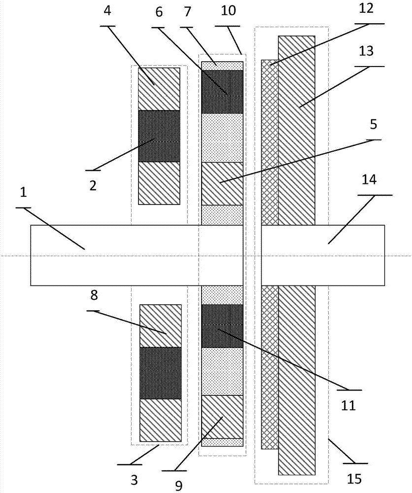
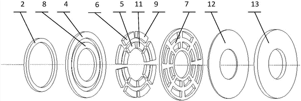
[0020] Such as figure 1 As shown, the disc type translation permanent magnet stator type permanent magnet eddy current speed regulating device provided by the present invention, a kind of disk type translation permanent magnet stator type permanent magnet eddy current speed regulating device, includes an input shaft 1 and an output shaft 14 arranged concentrically, and the input A permanent magnet stator 3 and a magnetic rotor 10 are sequentially arranged concentrically on the shaft 1 along its axial direction, the permanent magnet stator 3 can be translated along the axial direction of the input shaft 1, and a conductor rotor 15 is arranged concentrically on ...


PUM


Abstract

The invention discloses a disk type translation permanent magnetic stator type permanent magnetic vortex speed regulating device. The device comprises an input shaft and an output shaft in a concentric arrangement. The input shaft is orderly and concentrically provided with a permanent magnet stator and a magnetic rotor along an axial direction. The permanent magnet stator can translate along the axial direction of the input shaft. The output shaft is concentrically provided with a conductor rotor. The permanent magnet stator comprises an outer ring iron core, a radially magnetized permanent magnet ring and an inner ring iron core nested in order. The magnetic rotor comprises inner and outer ring permanent magnet poles which are in a staggered arrangement along a circumferential direction. Both the inner and outer ring permanent magnet poles are in an interval arrangement with corresponding iron poles, and the polarities of the inner and outer ring permanent magnet poles are the opposite. Compared with the prior art, the device of the invention has the advantages that through axially translating the permanent magnet stator, a speed adjustment function is realized, thus a speed regulating mechanism is simplified, the maintenance cost is reduced, the service life is prolonged, the structure is simple, the operation is convenient, the device is suitable for the occasions of different requirements, and the device has the functions of a permanent magnet coupling coupler, a soft starter and a permanent magnet speed regulator.

Description

technical field [0001] The invention belongs to the technical field of electric motor manufacturing, and relates to a permanent magnet eddy current speed regulating device of a disc type translational permanent magnet stator. Background technique [0002] With the popularization and application of high-performance permanent magnet materials, the permanent magnet speed control technology has been rapidly developed. It is a new type of speed control and energy saving technology for motor drive systems. There is no contact between the prime mover and the load, no vibration transmission and axis offset problems. , thereby greatly improving system reliability. The application of permanent magnet transmission technology has a history of several decades. Its application is to realize the non-contact transmission of torque between the prime mover and the load through magnetic field coupling. Mainly used in the chemical industry, petrochemical industry, coal cement, metallurgy, stee...

Claims


Application Information

Patent Timeline
Patent Type & Authority Applications(China)
IPC IPC(8): H02K49/10
CPCH02K49/108
Inventor 林鹤云李毅搏阳辉王海涛房淑华
Owner SOUTHEAST UNIV
Why Eureka
Try Eureka