Optical signal transmitting end and millimeter wave radio-over-fiber communication system

An optical signal and transmitter technology, applied in the field of millimeter wave generation, can solve the problems of millimeter wave quality deterioration, optical signal power drop, and large power difference, and achieve the effects of reducing optical power ratio, power balance, and low cost

Active Publication Date: 2017-06-20
ZHONGTIAN COMM TECH CO LTD +2
View PDF4 Cites 2 Cited by
  • Summary
  • Abstract
  • Description
  • Claims
  • Application Information

AI Technical Summary

Problems solved by technology

[0003] In the prior art, the optical signal transmitting end usually modulates the original optical wave generated by the laser through an external modulator to obtain multiple coherent optical carriers, and then selects the required two optical carriers through WSS (Wavelength Selective Switch), one of which is optical The carrier does not undergo any processing to obtain an unmodulated optical signal. Another optical carrier is input into the baseband data modulator to modulate the baseband data to obtain a modulated optical signal. However, after the optical wave is modulated by the modulator, the power of the optical signal will decrease. If the drop is obvious, the optical carrier finally output by the baseband data modulator is the optical carrier obtained after being modulated by two modulators, the external modulator and the baseband data modulator. Large, which makes the quality of the millimeter wave obtained after the final beat frequency of the two optical carriers deteriorates

Method used


Image

  • Optical signal transmitting end and millimeter wave radio-over-fiber communication system
  • Optical signal transmitting end and millimeter wave radio-over-fiber communication system
  • Optical signal transmitting end and millimeter wave radio-over-fiber communication system

Examples


Embodiment Construction

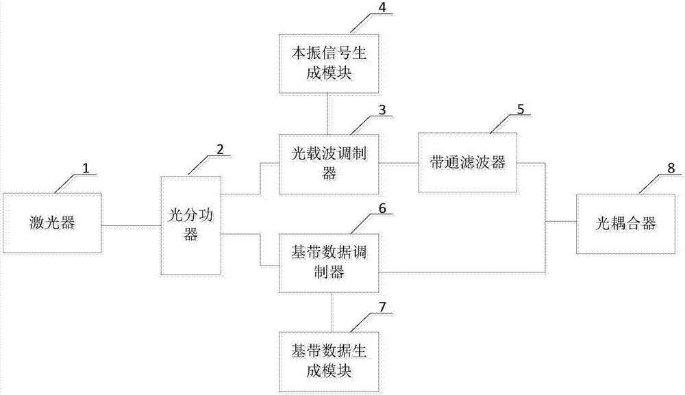
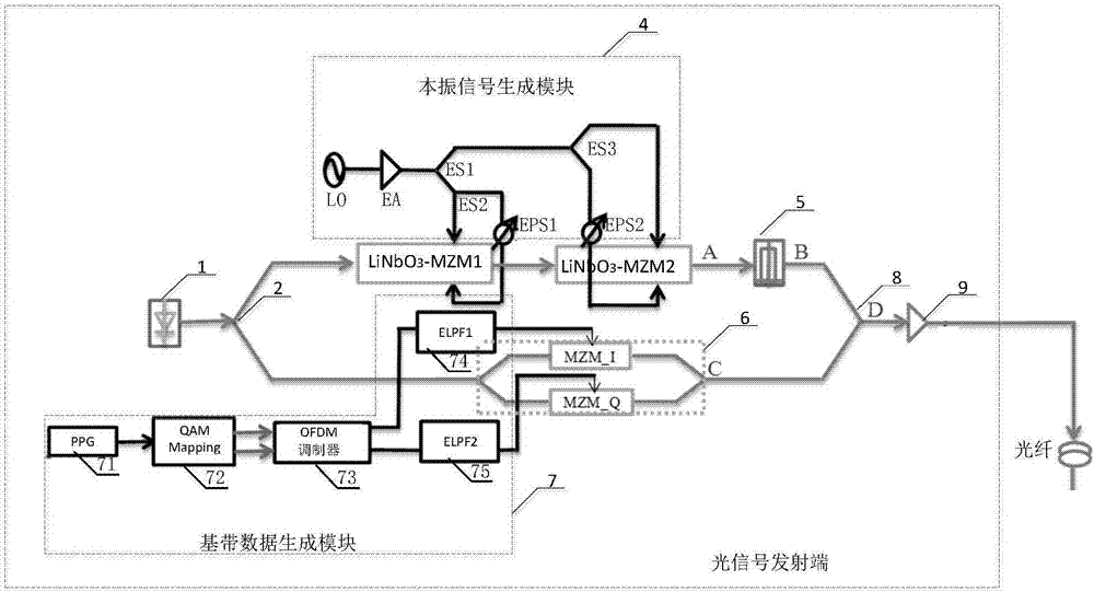
[0039]The core of the present invention is to provide an optical signal transmitting end. On the one hand, compared with the wavelength selective switch, the price of the optical power splitter is relatively cheap, and the cost is low; The output original light wave is divided into power, so as to directly provide a high-power light wave for the baseband data modulator in one optical path for baseband data modulation, and also take into account the insertion loss of the modulator and filter in the other optical path, which is relatively Balancedly provide light waves for the modulators in the following two paths, so that the power of the two optical signals coupled by the optical coupler is relatively balanced, reducing the optical power ratio, thereby improving the quality of the millimeter wave; another core of the present invention is Provided is a millimeter-wave optical carrier wireless communication system comprising the above-mentioned optical signal transmitting end, wh...


PUM


Abstract

The invention discloses an optical signal transmitting end and a millimeter wave radio-over-fiber communication system. The optical signal transmitting end comprises a laser device, an optical power splitter, a local oscillator signal generation module, an optical carrier wave modulator, a band pass filter, a base-band data generation module, a base-band data modulator and an optical coupler, wherein the laser device is connected with an input end of the optical power splitter, a first output end of the optical power splitter is connected with the optical carrier wave modulator, a second output end of the optical power splitter is connected with the base-band data modulator, the optical carrier wave modulator is also connected with a local oscillator signal output module and the band pass filter, the base-band data modulator is also connected with the base-band data generation module, and the optical coupler is connected with the band pass filter and the base-band data modulator. According to the optical signal transmitting end, the optical power splitter is arranged at an output end of the laser device, the optical power splitter is low in price and cost, original light waves output by the laser device can be subjected to power splitting operation via the optical power splitter, two optical signals coupled via the optical coupler are enabled to be equal in power, and therefore millimeter waves can be improved in quality.

Description

technical field [0001] The present invention relates to the technical field of millimeter wave generation, in particular to an optical signal transmitter and a millimeter wave light-borne wireless communication system. Background technique [0002] With the explosive growth of communication services in the 5G era, millimeter waves have received more and more attention and research because they can provide huge frequency bandwidth and minimize interference with existing wireless communication services. . The millimeter-wave light-borne wireless communication system uses optical methods to generate high-frequency millimeter waves, and because the loss of optical fibers used to transmit optical signals is small, the system can transmit optical signals to far away places, and uses photoelectric detection at the receiving end Millimeter waves can be obtained by beating the frequency of the optical signal. [0003] In the prior art, the optical signal transmitting end usually mo...

Claims


Application Information

Patent Timeline
Patent Type & Authority Applications(China)
IPC IPC(8): H04B10/564H04B10/50
CPCH04B10/503H04B10/564Y02D30/70
Inventor 高明义杨涛
Owner ZHONGTIAN COMM TECH CO LTD
Why Eureka
Try Eureka