Electrical control equipment cabinet with multiple heat dissipation functions

An electrical control equipment, multiple heat dissipation technology, applied in the field of control cabinets, can solve the problems of insufficient energy saving and environmental protection, traditional structure, dust safety hazards, etc., and achieve the effect of good cooling effect

Inactive Publication Date: 2017-06-20
李俊娴
View PDF4 Cites 12 Cited by
  • Summary
  • Abstract
  • Description
  • Claims
  • Application Information

AI Technical Summary

Problems solved by technology

[0002] With the development of science and technology, there are more and more applications of automatic control electrical appliances on equipment, especially some high-tech and precision electrical appliances are more widely used. Because electrical appliances have static electricity during work, dust in the air will The threat to the safe operation of the electrical automation control cabinet is serious. In order to prevent the dust pollution of electrical appliances, the existing electrical automation control cabinet usually installs vacuum cleaners and other equipment in the electrical automation contro

Method used


Image

  • Electrical control equipment cabinet with multiple heat dissipation functions
  • Electrical control equipment cabinet with multiple heat dissipation functions
  • Electrical control equipment cabinet with multiple heat dissipation functions

Examples


Embodiment Construction

[0021] The following will clearly and completely describe the technical solutions in the embodiments of the present invention with reference to the accompanying drawings in the embodiments of the present invention. Obviously, the described embodiments are only some, not all, embodiments of the present invention. Based on the embodiments of the present invention, all other embodiments obtained by persons of ordinary skill in the art without making creative efforts belong to the protection scope of the present invention.

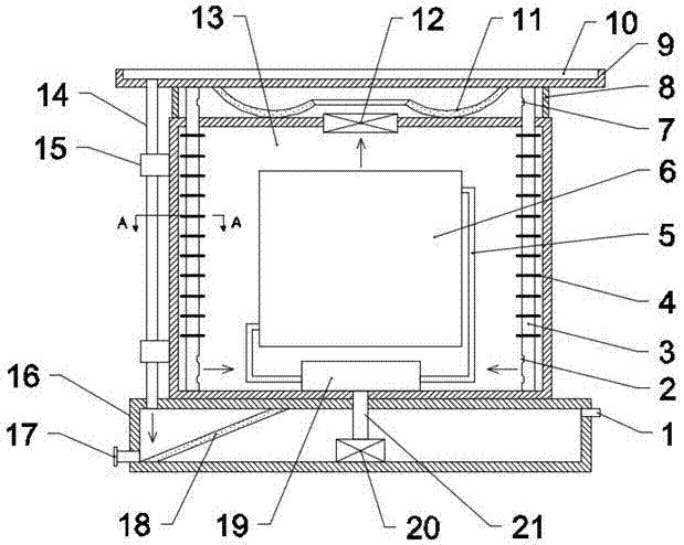
[0022] see Figure 1~4 , in an embodiment of the present invention, an electrical control equipment cabinet with multiple heat dissipation functions includes a cabinet body 13, a top plate 9 is provided above the cabinet body 13, and a support tube is provided on the outside between the top plate 9 and the cabinet body 13 8. The upper end of the support tube 8 is sealed and connected to the top plate 9, and the lower end of the support tube 8 is sealed and con...


PUM

PropertyMeasurementUnit
Thicknessaaaaaaaaaa

Abstract

The invention discloses an electrical control equipment cabinet with multiple heat dissipation functions. The cabinet comprises a cabinet body. A roof is arranged on the top of the cabinet. A support cylinder is arranged outside the space between the roof and the cabinet body. A water tank is arranged at the bottom of the cabinet body. A water delivery pipe is arranged at the bottom of the left side of the roof. The lower end of the water delivery pipe is fixed to the top of the water tank. A cooling fan is installed at a middle gap in the top of the cabinet body. A snakelike through cooling pipe is arranged inside an electrical equipment mounting plate in the cabinet body. The two ends of the cooling pipe are respectively communicated with the two sides of a cooling device arranged at the inner bottom of the cabinet body. A water pump is arranged at the inner bottom of the water tank. The upper end of a water supply pipe of the water pump is connected with the cooling device. A ventilation pipe is arranged at each of the four corners of the inner side of the cabinet body. Multiple radiating fins are arranged on the ventilation pipes inside the cabinet body. There are a variety of heat dissipation modes. The electrical control equipment cabinet is energy-saving and environment-friendly. Dust can be removed in the process of heat dissipation. Isolation from the outside air is achieved. Stable operation of electrical equipment can be maintained.

Description

technical field [0001] The invention relates to the technical field of control cabinets, in particular to an electrical control equipment cabinet with multiple cooling functions. Background technique [0002] With the development of science and technology, there are more and more applications of automatic control electrical appliances on equipment, especially some high-tech and precision electrical appliances are more widely used. Because electrical appliances have static electricity during work, dust in the air will The threat to the safe operation of the electrical automation control cabinet is serious. In order to prevent the dust pollution of electrical appliances, the existing electrical automation control cabinet usually installs vacuum cleaners and other equipment in the electrical automation control cabinet. Although this method can reduce the dust content in the electrical automation control cabinet, the vacuum cleaner Such equipment occupies a large amount of inter...

Claims


Application Information

Patent Timeline
IPC IPC(8): H05K5/06H05K7/20
CPCH05K5/069H05K7/20136H05K7/20272H05K7/20409
Inventor 李俊娴
Owner 李俊娴
Why Eureka
Try Eureka