High-efficiency filtration device for petroleum
A high-efficiency filtration and filtration device technology, which is applied in the direction of filtration separation, filtration circuit, and purification by filtration, can solve the problems of inconvenient use, poor filtration effect, and easy blockage
- Summary
- Abstract
- Description
- Claims
- Application Information
AI Technical Summary
Problems solved by technology
Method used
Image

Examples
Embodiment 1
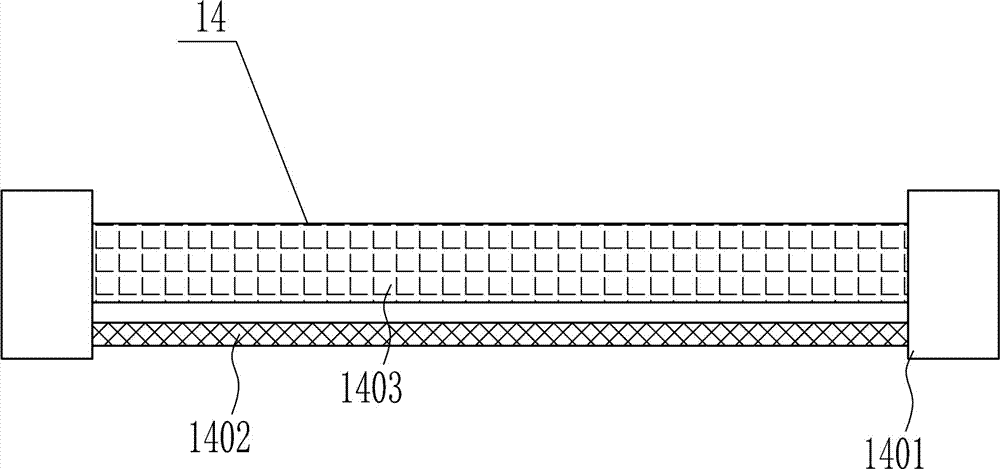
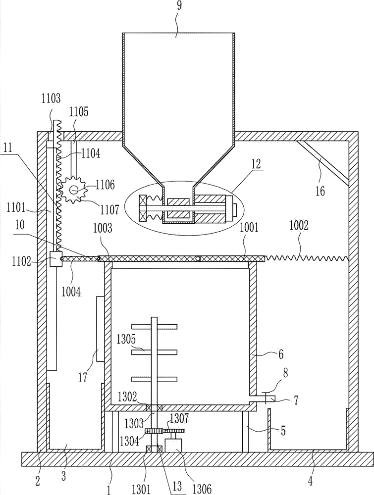
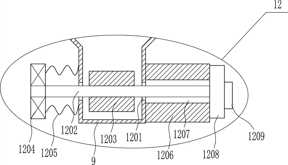
[0038] A high-efficiency oil filter device, such as Figure 1-8 As shown, it includes a bottom plate 1, an n-type bracket 2, an impurity collection frame 3, an oil collection frame 4, a first pole 5, an oil collection box 6, a discharge pipe 7, a valve 8, a lower hopper 9, and a first filter device 10. The driving device 11 and the throttling device 12, the top of the bottom plate 1 is provided with an n-type bracket 2, the left and right sides of the top of the bottom plate 1 are respectively placed with an impurity collection frame 3 and an oil collection frame 4, between the impurity collection frame 3 and the oil collection frame 4 The top of the bottom plate 1 between them is symmetrically welded with the first support rod 5, the top of the first support rod 5 is welded with the oil collection box 6, the oil collection box 6 has a discharge port, and the lower right side of the oil collection box 6 is welded with a discharge port. The pipe 7 and the discharge pipe 7 are p...
Embodiment 2
[0040] A high-efficiency oil filter device, such as Figure 1-8 As shown, it includes a bottom plate 1, an n-type bracket 2, an impurity collection frame 3, an oil collection frame 4, a first pole 5, an oil collection box 6, a discharge pipe 7, a valve 8, a lower hopper 9, and a first filter device 10. The driving device 11 and the throttling device 12, the top of the bottom plate 1 is provided with an n-type bracket 2, the left and right sides of the top of the bottom plate 1 are respectively placed with an impurity collection frame 3 and an oil collection frame 4, between the impurity collection frame 3 and the oil collection frame 4 The top of the bottom plate 1 between them is symmetrically welded with the first support rod 5, the top of the first support rod 5 is welded with the oil collection box 6, the oil collection box 6 has a discharge port, and the lower right side of the oil collection box 6 is welded with a discharge port. The pipe 7 and the discharge pipe 7 are p...
Embodiment 3
[0043] A high-efficiency oil filter device, such as Figure 1-8 As shown, it includes a bottom plate 1, an n-type bracket 2, an impurity collection frame 3, an oil collection frame 4, a first pole 5, an oil collection box 6, a discharge pipe 7, a valve 8, a lower hopper 9, and a first filter device 10. The driving device 11 and the throttling device 12, the top of the bottom plate 1 is provided with an n-type bracket 2, the left and right sides of the top of the bottom plate 1 are respectively placed with an impurity collection frame 3 and an oil collection frame 4, between the impurity collection frame 3 and the oil collection frame 4 The top of the bottom plate 1 between them is symmetrically welded with the first support rod 5, the top of the first support rod 5 is welded with the oil collection box 6, the oil collection box 6 has a discharge port, and the lower right side of the oil collection box 6 is welded with a discharge port. The pipe 7 and the discharge pipe 7 are p...
PUM
 Abstract
Description
Claims
Application Information
 - Generate Ideas
- Intellectual Property
- Life Sciences
- Materials
- Tech Scout
- Unparalleled Data Quality
- Higher Quality Content
- 60% Fewer Hallucinations
Browse by: Latest US Patents, China's latest patents, Technical Efficacy Thesaurus, Application Domain, Technology Topic, Popular Technical Reports.
© 2025 PatSnap. All rights reserved.Legal|Privacy policy|Modern Slavery Act Transparency Statement|Sitemap|About US| Contact US: help@patsnap.com