Positioning assembly, device and method for reserved joint bars in shear wall

A positioning component and positioning device technology, which is applied in the processing of building materials, construction, building construction, etc., can solve the problems of low construction efficiency, difficulty in controlling the positioning of reserved ribs, and poor precision, so as to improve construction efficiency and facilitate construction. The effect of convenient control, adjustment and positioning process

Pending Publication Date: 2017-06-23
SHANGHAI NO 4 CONSTR
View PDF5 Cites 8 Cited by
  • Summary
  • Abstract
  • Description
  • Claims
  • Application Information

AI Technical Summary

Problems solved by technology

[0004] Aiming at the problems of the existing overall prefabricated steel mesh construction technology, the positionin

Method used


Image

  • Positioning assembly, device and method for reserved joint bars in shear wall
  • Positioning assembly, device and method for reserved joint bars in shear wall
  • Positioning assembly, device and method for reserved joint bars in shear wall

Examples


Example Embodiment

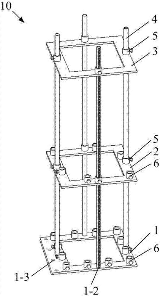
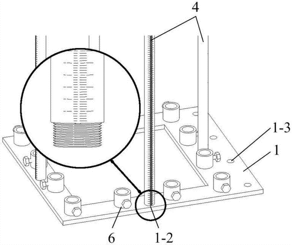
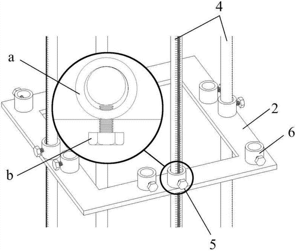
[0046] Embodiment 1: This embodiment takes the construction of the vertical reserved inserts in the reinforced concrete shear wall as an example, and combines Figure 1 to Figure 4 Describe the specific structure and connection relationship of the positioning assembly 10 with the ribs reserved in the shear wall of the present invention. The positioning assembly 10 includes a first limit frame 1 and a second limit frame 2 arranged at intervals from bottom to top and coaxial. And the third limit frame 3, and several support rods 4, the support rod 4 penetrates the second limit frame 2 and the support rod fixing pins 5 on the third limit frame 3 and is movably connected with the first limit frame 1, and The support rod 4 is provided with a scale, and the first limit frame 1 and the second limit frame 2 are also provided with a plurality of rib fixing pins 6.

[0047] The positioning assembly 10 with reserved inserts in the shear wall of the present invention includes a first limit fr...

Example Embodiment

[0051] Embodiment 2: Combination Figure 5 with Image 6 It is explained that the positioning device 100 for pre-insertion ribs in the shear wall of the present invention includes at least two positioning assemblies 10 arranged side by side, and the first limit frames 1 of two adjacent positioning assemblies 10 are connected by a connecting frame 20 by bolts. Specifically, one side of the first limit frame 1 of the positioning assembly 10 is provided with a number of bolt holes 21-3, and two ends of the connecting frame 20 are provided with bolt holes 321 corresponding to the bolt holes 21-3, so that The connecting frame 20 can be bolted to the first limit frame 1 located on both sides thereof.

[0052] The positioning device 100 with reserved inserts in the shear wall of the present invention bolts two adjacent positioning components 10 into an integral support structure through the connecting frame 20. The support structure and the adjustable and readable support rod 4 are used ...

Example Embodiment

[0054] Example 3: Combination Figure 7 to Figure 19 To illustrate the positioning method of the reserved inserts in the shear wall of the present invention, the specific steps are as follows:

[0055] One, such as Figure 7 As shown, two first limit frames 1 arranged side by side are installed and fixed on the foundation slab (not shown in the figure) or the reinforced mesh W that has been constructed, so that the two ends of the connecting frame 20 are connected to the two first limit frames respectively. Frame 1 bolt connection;

[0056] Two, such as Figure 8 As shown, a number of support rods 4 are installed so that the bottom end of the support rod 4 is movably connected with the first limit frame 1;

[0057] Three, such as Picture 9 with Picture 10 As shown, the second limit frame 2 and the third limit frame 3 are sequentially sleeved on the support rod 4, and the fastening bolt b on the support rod fixing pin 5 is tightened, so that the support rod 4 is firmly connected to ...


PUM


Abstract

The invention discloses a positioning assembly, device and method for reserved joint bars in a shear wall, and relates to the technical field of constructional engineering. In order to solve the problems that according to an existing overall prefabricated reinforcing mesh building technology, reserved joint bar positioning is hard to control, precision is poor, and construction efficiency is low, the positioning assembly comprises a first limiting frame, a second limiting frame, a third limiting frame and a supporting rod, wherein the first, second and third limiting frames are arranged coaxially in a spaced mode, the supporting rod penetrates through supporting rod fixing pins of the second and third limiting frames and is movably connected with the first limiting frame, scale marks are arranged on the supporting rod, and a plurality of joint bar fixing pins are arranged on the first and second limiting frames. The positioning device comprises at least two positioning assemblies arranged in parallel. The positioning assemblies are connected through connecting frame bolts. The positioning method comprises the steps that the positioning device is installed on a constructed reinforcing mesh, reserved joint bars and middle joint bars are positioned and installed, and the positioning device is disassembled.

Description

technical field [0001] The invention relates to the technical field of construction engineering, in particular to a positioning component, a positioning device and a positioning method for inserting ribs reserved in a shear wall. Background technique [0002] Reinforced concrete shear walls have the advantages of high bearing capacity, good ductility, and good economy, so they are widely used in high-rise and super high-rise buildings. The traditional cast-in-place process of reinforced concrete shear walls is to manually bind the steel bars one by one at the construction site, and then seal the mold and pour the concrete. This construction mode has the disadvantages of inaccurate positioning of the steel bars, difficulty in ensuring the quality of the steel bar binding, heavy on-site workload, and a long construction period. Defects such as low construction efficiency. [0003] The overall prefabricated steel mesh construction process solves many problems existing in the t...

Claims


Application Information

Patent Timeline
IPC IPC(8): E04G21/12
CPCE04G21/12
Inventor 汪小林张铭黄轶谷志旺李晓青张云超陈辉
Owner SHANGHAI NO 4 CONSTR
Why Eureka
Try Eureka