
Rankine Cycle System For Vehicle

A circulation system and vehicle technology, applied in the field of Rankine cycle system for vehicles

Active Publication Date: 2017-06-23
TOYOTA JIDOSHA KK
View PDF8 Cites 0 Cited by
  • Summary
  • Abstract
  • Description
  • Claims
  • Application Information

AI Technical Summary

Problems solved by technology

In the above-mentioned technologies, the structure of mounting the Rankine cycle system on a mobile body such as a vehicle has not been considered, and there is still room for improvement in the point of suppressing the vibration of the vehicle

Method used


Image

  • Rankine Cycle System For Vehicle
  • Rankine Cycle System For Vehicle
  • Rankine Cycle System For Vehicle

Examples


Embodiment approach 1

[0057] 1. Structure of the Rankine cycle system

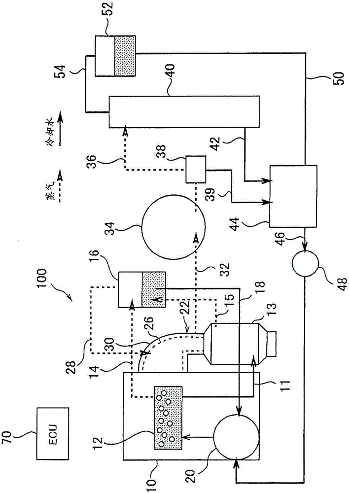
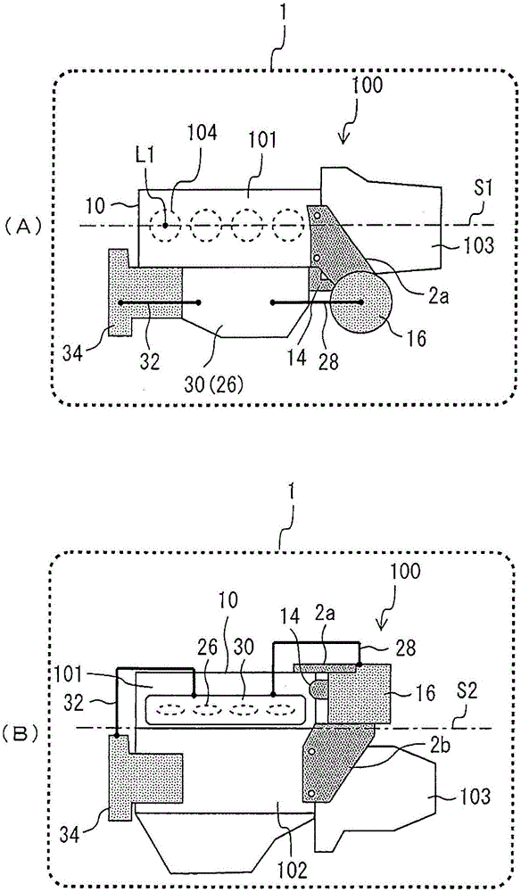
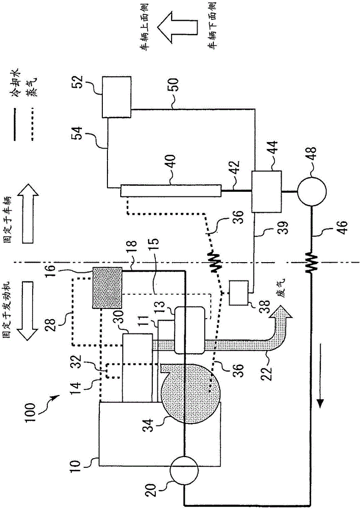
[0058] figure 1 It is a figure which shows the structure of the Rankine cycle system 100 of Embodiment 1. The Rankine cycle system 100 of Embodiment 1 is configured as a vehicular Rankine cycle system mounted on a vehicle including an internal combustion engine (engine) 10 . The type and structure of the engine 10 are not limited. However, in the cylinder block and the cylinder head of the engine 10 , a refrigerant flow path 12 through which the refrigerant circulating in the engine 10 flows is formed. The refrigerant flow path 12 includes a water jacket surrounding the cylinder. Engine 10 is cooled by heat exchange with the refrigerant flowing in refrigerant passage 12 . In this embodiment, water is used as the refrigerant.

[0059] The engine 10 is cooled by using waste heat of the engine 10 to boil the refrigerant flowing through the refrigerant passage 12 to vaporize part of the refrigerant. That is, the refrigerant p...


PUM


Abstract

A Rankine cycle system includes a boiler configured to apply waste heat to refrigerant circulating in an internal-combustion engine to vaporize the refrigerant; a gas-liquid separator configured to separate gas-liquid two-phase refrigerant, sent from the boiler, into gas phase fluid and liquid phase fluid; a superheater configured to superheat the gas phase fluid, sent from the gas-liquid separator, through heat exchange with exhaust gas of the internal-combustion engine; an expander configured to expand the gas phase fluid, passing through the superheater, to recover thermal energy, and a condenser configured to condense the gas phase fluid, passing through the expander, to return the gas phase fluid to liquid phase fluid. The gas-liquid separator is connected to the internal combustion engine via a refrigerant pipe. The internal combustion engine is fixed onto an engine mount of a vehicle. The gas-liquid separator is fixed to the internal combustion engine via a bracket.

Description

technical field [0001] The present invention relates to a Rankine cycle system for a vehicle, and more particularly to a structure for mounting the Rankine cycle system on a vehicle. Background technique [0002] Patent Document 1 discloses a technique related to a Rankine cycle system mounted on a vehicle. In this Rankine cycle system, waste heat from the engine is used to boil a liquid-phase fluid into a gas-phase fluid, expand the gas-phase fluid to obtain work, and condense the expanded gas-phase fluid to return to a liquid-phase fluid. [0003] prior art literature [0004] patent documents [0005] Patent Document 1: Japanese Patent Laid-Open No. 2015-94271 [0006] Patent Document 2: Japanese Patent Laid-Open No. 2002-316530 [0007] Patent Document 3: Japanese Patent Laid-Open No. 2011-189824 [0008] The Rankine cycle system has a structure in which various structural elements are connected by piping or the like. In particular, the gas-liquid separator, which ...

Claims


Application Information

Patent Timeline
Patent Type & Authority Applications(China)
IPC IPC(8): F02G5/00
CPCF02G5/00F01K23/065F01K23/10F05D2220/62H02K7/1823
Inventor 立野学
Owner TOYOTA JIDOSHA KK
Learn More