
Air conditioner and control method thereof

A control method and technology of an air conditioner, applied in the direction of control input involving air characteristics, space heating and ventilation control input, heating and ventilation control system, etc., can solve problems such as poor comfort and long defrosting time, and achieve Effects of increased exhaust pressure, increased exhaust temperature, and rapid heating of the refrigerant

Pending Publication Date: 2017-06-23
GD MIDEA AIR-CONDITIONING EQUIP CO LTD +1
View PDF3 Cites 7 Cited by
  • Summary
  • Abstract
  • Description
  • Claims
  • Application Information

AI Technical Summary

Problems solved by technology

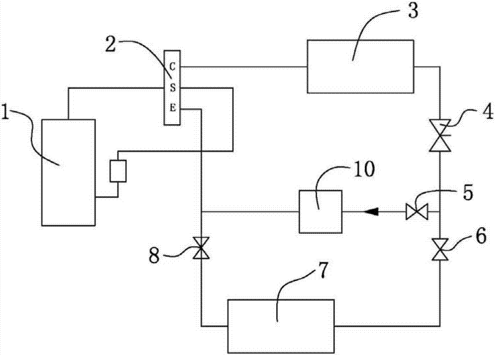
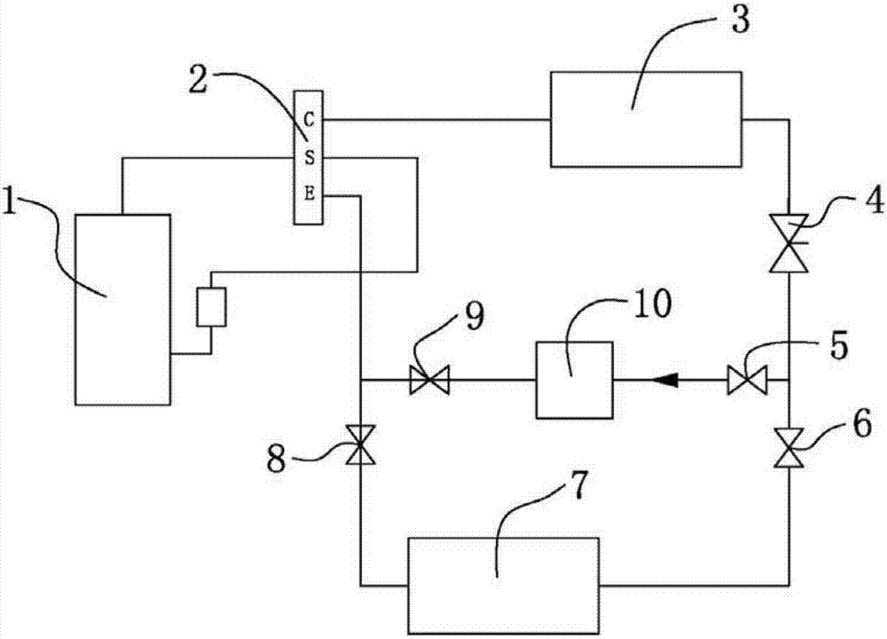
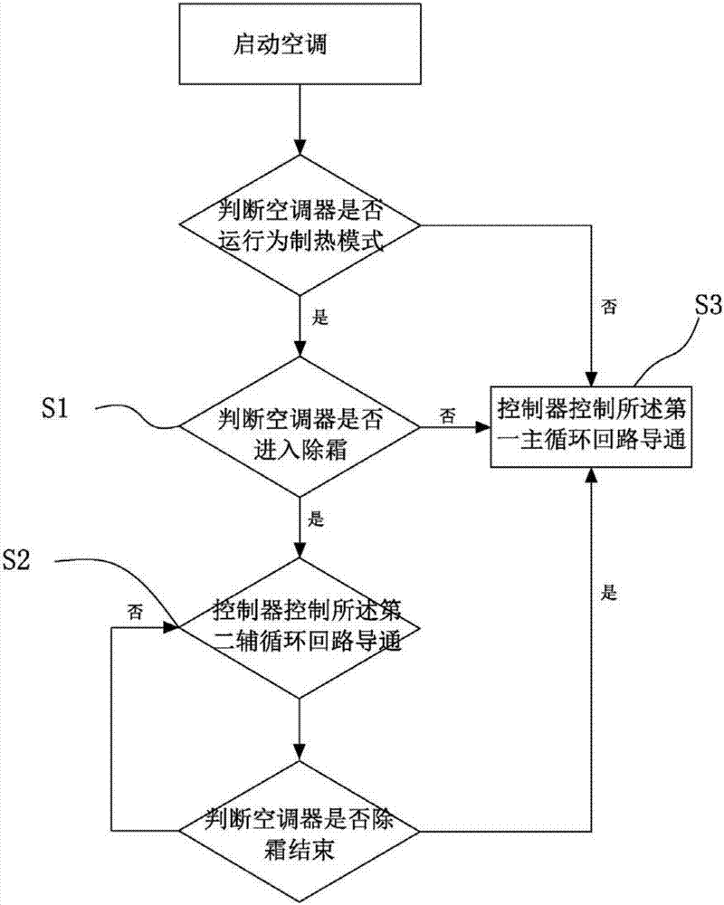
[0003] In order to solve the problems of poor comfort and long defrosting time of existing air conditioners, the present invention provides an air conditioner and its control method. By adding a second auxiliary circulation loop and a heating device, the air conditioner can High efficiency, reducing defrosting time and improving air conditioner comfort

Method used


Image

  • Air conditioner and control method thereof
  • Air conditioner and control method thereof
  • Air conditioner and control method thereof

Examples


Embodiment Construction

[0027] It should be understood that the specific embodiments described here are only used to explain the present invention, not to limit the present invention.

[0028] The following will clearly and completely describe the technical solutions in the embodiments of the present invention with reference to the accompanying drawings in the embodiments of the present invention. Obviously, the described embodiments are only part of the embodiments of the present invention, not all of them. Based on the embodiments of the present invention, all other embodiments obtained by persons of ordinary skill in the art without creative efforts fall within the protection scope of the present invention.

[0029] It should be noted that all directional indications (such as up, down, left, right, front, back...) in the embodiments of the present invention are only used to explain the relationship between the components in a certain posture (as shown in the accompanying drawings). Relative positi...


PUM


Abstract

The invention discloses an air conditioner. The air conditioner comprises a refrigeration or heating first main circulation loop and a second auxiliary circulation loop. The refrigeration or heating first main circulation loop is formed by sequentially connecting a compressor, a four-way reversing valve, an indoor heat exchanger, a throttle element and an outdoor heat exchanger in series. The second auxiliary circulation loop is arranged between the throttle element and the four-way reversing valve. The first main circulation loop further comprises a third solenoid valve and a fourth solenoid valve which are connected in refrigerant flow paths of the indoor heat exchanger. The first main circulation loop is controlled to be turned on and off through the third solenoid valve and the fourth solenoid valve. The second auxiliary circulation loop comprises a first solenoid valve and a heating device which are sequentially connected in series. The input end of the first solenoid valve is connected into the flow path of refrigerant throttled by the throttle element, and the output end of the heating device is connected into the flow path of refrigerant flowing out of the indoor heat exchanger. The second auxiliary circulation loop is controlled to be turned on and off through the first solenoid valve. According to the air conditioner, the second auxiliary circulation loop and the heating device are additionally arranged, and therefore the air conditioner is efficient during defrosting, the defrosting time is reduced, and the comfort of the air conditioner is improved.

Description

technical field [0001] The invention relates to the technical field of intelligent air conditioners, and more specifically, the invention relates to an air conditioner and a control method thereof. Background technique [0002] At present, when the air conditioner is running for heating in a low temperature environment, because the outdoor ambient temperature is very low, the condenser will be full of frost after a period of operation, and the air conditioner system will perform defrosting treatment at this time. During the defrosting period (ranging from 3 to 10 minutes), the indoor unit is turned off, and the air conditioner system is in the cooling mode, and it will not enter the heating mode again until the defrosting is completely completed. Obviously, during the defrosting period, the air conditioner cannot provide heating, which seriously affects the user's comfort and satisfaction. Contents of the invention [0003] In order to solve the problems of poor comfort a...

Claims


Application Information

Patent Timeline
Patent Type & Authority Applications(China)
IPC IPC(8): F25B13/00F25B47/02F25B49/02F24F11/00
CPCF24F11/30F24F2110/10F25B13/00F25B47/022F25B49/02F24F11/42F25B2313/02741F25B2600/25F25B2700/11
Inventor 吴杨杨
Owner GD MIDEA AIR-CONDITIONING EQUIP CO LTD
Learn More