Engine correct timing system inspection tool and method thereof

A timing system and engine technology, used in engine testing, measuring devices, internal combustion engine testing, etc., can solve problems such as oil leakage, reduced gasket sealing, and poor sealing, reducing workload, improving work efficiency, The effect of reducing the risk of oil spills

Inactive Publication Date: 2017-06-23
CHONGQING CHANGAN AUTOMOBILE CO LTD
View PDF11 Cites 3 Cited by
  • Summary
  • Abstract
  • Description
  • Claims
  • Application Information

AI Technical Summary

Problems solved by technology

In the process of disassembly and assembly, if the scraping glue does not meet the requirements or the sealing performance of the gasket is reduced, it will lead to poor sealing and oil leakage

Method used


Image

  • Engine correct timing system inspection tool and method thereof
  • Engine correct timing system inspection tool and method thereof
  • Engine correct timing system inspection tool and method thereof

Examples


Embodiment Construction

[0025] The present invention will be further described below in conjunction with accompanying drawing.

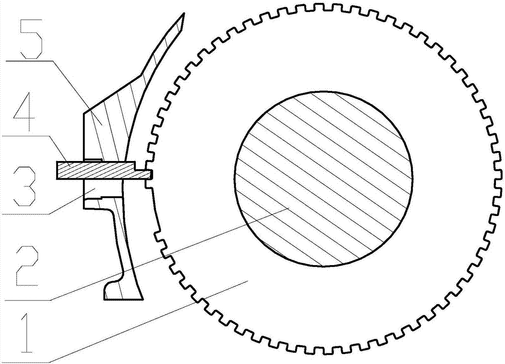
[0026] Such as Figure 1 to Figure 6 The engine timing system inspection tool shown includes a crankshaft position fixing part 4 and a camshaft phase inspection part 8 .

[0027] Such as Figure 4 As shown, the crankshaft position fixing member 4 includes a crankshaft position fixing body 43, and one end of the crankshaft position fixing body 43 is provided with a boss 41 matching the notch on the edge of the signal plate 1, and the top surface of the boss 41 is from The direction from the inside to the outside is inclined downward, so that the boss 41 can be inserted into the notch on the edge of the signal plate 1 conveniently. A projection 42 for fixing the position of the crankshaft 2 is provided on the top surface of the crankshaft position fixing body 43 .

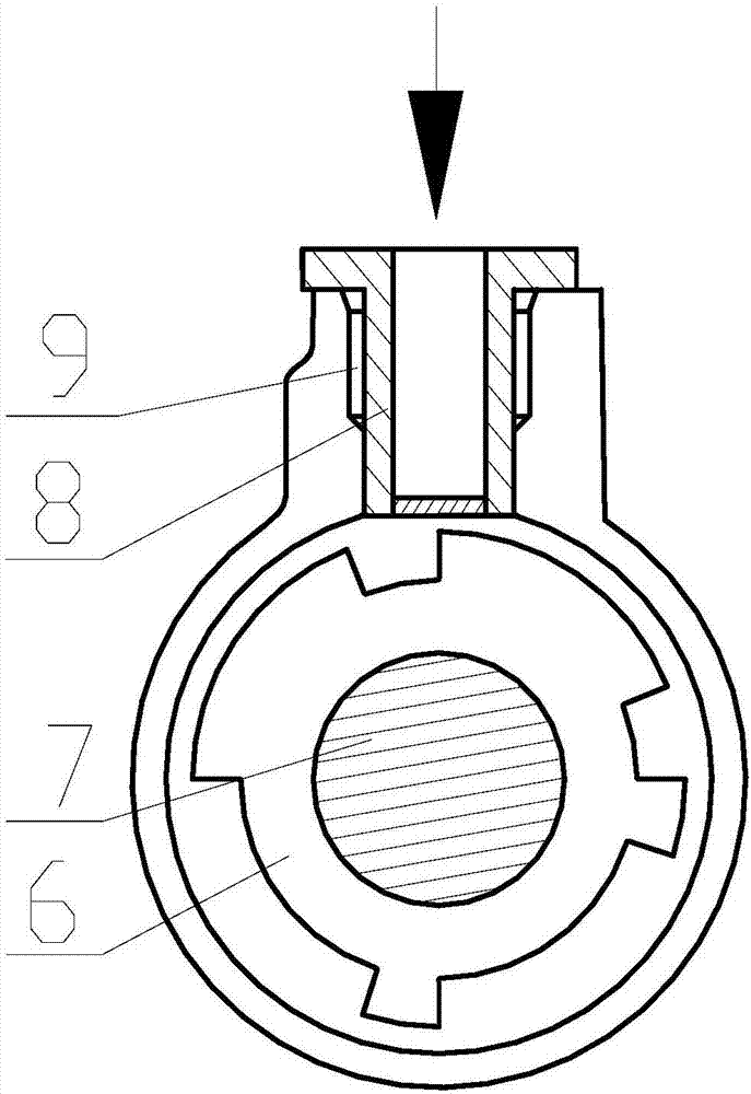
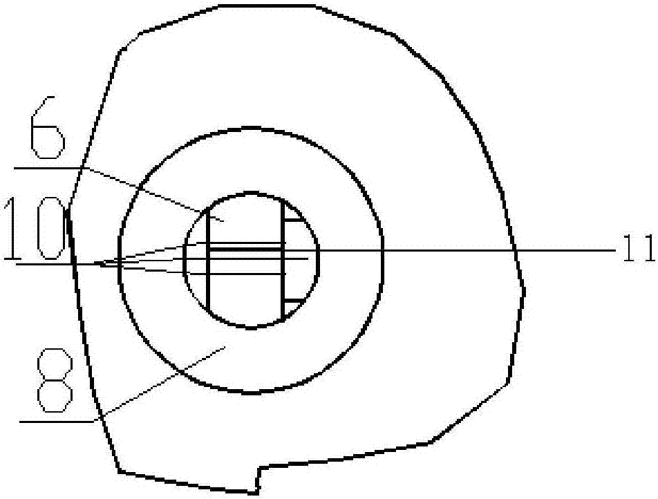
[0028] Such as Figure 5 with Image 6 As shown, the camshaft phase inspection part 8 is a cylindrical bod...


PUM


Abstract

The invention discloses an engine correct timing system inspection tool. The inspection tool comprises a crankshaft position fixing component and a camshaft phase inspection component. The crankshaft position fixing component comprises a crankshaft position fixing body. One end of the crankshaft position fixing body is provided with a boss which is cooperated with a gap on a signal disc edge. A top surface of the crankshaft position fixing body is provided with a bump used for fixing a crankshaft position. The camshaft phase inspection component is a cylinder body whose bottom end is sealed. A top end of the cylinder body is provided with a step. A bottom of the cylinder body is made of a transparent material. The bottom of the cylinder body is marked with scales used for detecting a camshaft position. The invention also discloses an engine correct timing system inspection method. By using the tool and the method of the invention, a oil leakage risk of a correct time system is reduced and work efficiency is increased.

Description

technical field [0001] The invention belongs to an automobile engine inspection tool, in particular to an engine timing system inspection tool and a method. Background technique [0002] At present, the purpose of the inspection of the timing system of the automobile engine is to determine whether the phases corresponding to the camshaft and the crankshaft are correct, and to troubleshoot the timing system failure. [0003] The steps for an existing timing system inspection include: [0004] (1) Disassemble the parts covering the timing system one by one; since the phaser or gear connected to the intake and exhaust camshafts, the crankshaft or the crankshaft sprocket are connected with each other by a chain, so turning the crankshaft in the timing system, The relevant parts will follow the rotation; [0005] (2) Turn the crankshaft in the timing system, and observe whether the timing mark set on the phaser or gear connected to the intake and exhaust camshafts and the timin...

Claims


Application Information

Patent Timeline
Patent Type & Authority Applications(China)
IPC IPC(8): G01M15/02G01M15/05
CPCG01M15/02G01M15/05
Inventor 殷智勇闵龙郑科江方庆罗通刘建东
Owner CHONGQING CHANGAN AUTOMOBILE CO LTD
Why Eureka
Try Eureka