Porous ceramic heating body and atomizer

A technology of porous ceramics and heating element, applied in the field of atomizers, can solve the problems of falling off of heating components, increasing the amount of e-liquid, poor bonding strength, etc., and achieve the effects of increasing heating efficiency, safe and environmentally friendly service life, and long service life.

Pending Publication Date: 2022-02-15
SHENZHEN HANQINGDA TECH CO LTD
View PDF0 Cites 2 Cited by
  • Summary
  • Abstract
  • Description
  • Claims
  • Application Information

AI Technical Summary

Problems solved by technology

[0004] In order to overcome the shortcomings and deficiencies in the prior art, the object of the present invention is to provide a porous ceramic heating element. By setting the porous ceramic matrix into two parts, which are integrally formed into upper and lower parts, it further increases the penetration from the oil storage matrix to the mist. The amount of e-liquid per unit area of ​​the substrate can be reduced, and multiple oil storage tanks are recessed on the oil-conducting surface of the oil-storage substrate to increase the oil storage capacity and the contact area between the e-liquid and the oil-storage substrate, so that e-liquid can pass through the side of the oil-storage substrate The porous wall penetrates into the atomizing surface of the atomizing substrate for atomization, and the setting of printing or embedding the heating element on the atomizing surface can effectively solve the poor bonding strength between the porous ceramic substrate and the heating element in the past. During the application process, heating components are prone to problems such as falling off and cracking, and the porous ceramic also has the advantages of better high temperature resistance, longer service life, safety and environmental protection

Method used


Image

  • Porous ceramic heating body and atomizer
  • Porous ceramic heating body and atomizer
  • Porous ceramic heating body and atomizer

Examples


Embodiment 1

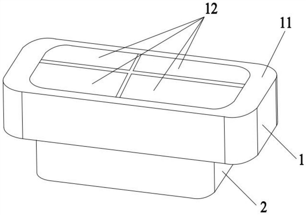
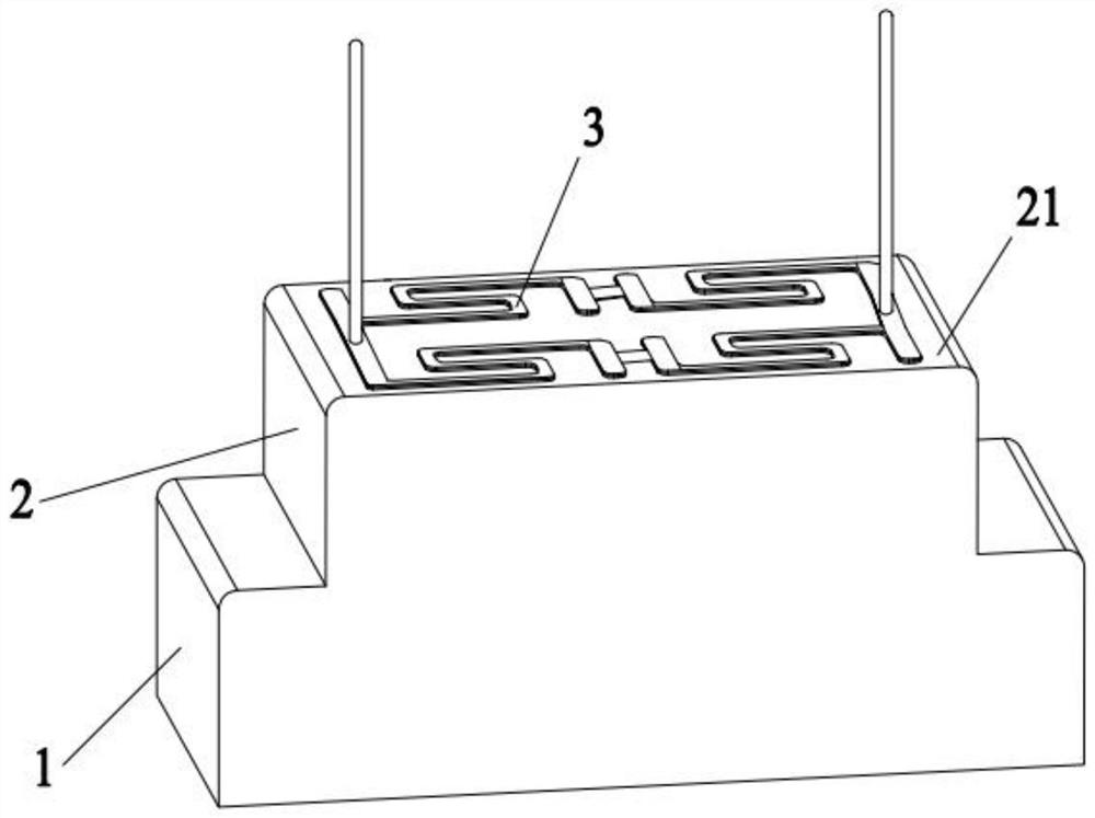
[0032] A porous ceramic heating element comprising a porous ceramic matrix, said ceramic matrix comprising a porous substrate and a reservoir substrate atomizing 12, the oil reservoir is provided on a base surface of the base body 2 is atomized, the oil reservoir surface of the base body 1 is the oil guide surface 11, the oil guide surface 11 is provided with a plurality of recessed sump 12, the lower surface of the base 2 of the atomizing surface 21 for atomization, the atomization surface 21 with a plurality of heat generating printed assembly 3, the position corresponding to the heat generating component 3 disposed in the sump 12, the sump 12 for placing the heat generating components 3, the reservoir 2 using a porous ceramic material and the base body 1 is integrally sintering atomized matrix . The sump 12 is provided at least two groups; the two are connected in parallel between the adjacent heat generating components 3.

[0033] The heat generating assembly 3 includes a heati...

Embodiment 2

[0045] A porous ceramic heat generating body comprising a porous ceramic substrate comprising an oil substrate 1 and an atomizing base 2, the oil storage base 1 is disposed on the upper surface of the atomizing base 2, the oil. The upper surface of the substrate 1 is a conducting surface 11, and the oil surface 11 is concave, and the lower surface of the atomization surface 21 is concave, and the atomization surface 21 is buried with several fever. As a member 3, the heat generating assembly 3 corresponds to the position of the oil storage tank 12, and the oil collecting base 1 and the atomization base 2 are integrally sintered with a porous ceramic material. The oil storage tank 12 is provided at least two groups; a connection between the two of the heat generating assemblies 3.

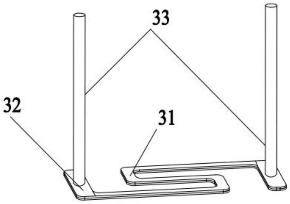
[0046] The heat generating assembly 3 includes a heating line 31, two resistive sheets 32, and two terminals 33, which are respectively connected to both ends of the heating line 31, respectively, respe...

Embodiment 3

[0058] A porous ceramic heat generating body comprising a porous ceramic substrate comprising an oil substrate 1 and an atomizing base 2, the oil storage base 1 is disposed on the upper surface of the atomizing base 2, the oil. The upper surface of the base body 1 is a conductive surface 11, and the oil surface 11 is concave, and the lower surface of the atomizing substrate 2 is atomized surface 21, and the atomization surface 21 is printed with several fever. As a member 3, the heat generating assembly 3 corresponds to the position of the oil storage tank 12, and the oil collecting base 1 and the atomization base 2 are integrally sintered with a porous ceramic material. The oil storage tank 12 is provided at least two groups; a connection between the two of the heat generating assemblies 3.

[0059] The heat generating assembly 3 includes a heating line 31, two resistive sheets 32, and two terminals 33, which are respectively connected to both ends of the heating line 31, respect...


PUM


Abstract

The invention relates to the technical field of atomizers, in particular to a porous ceramic heating element and an atomizer, the porous ceramic heating element comprises a porous ceramic base body, the porous ceramic base body comprises an oil storage base body and an atomizing base body, the oil storage base body is arranged on the upper surface of the atomizing base body, the upper surface of the oil storage base body is an oil guide surface, and an oil storage tank is concavely formed in the oil guide surface; and the lower surface of the atomizing base body is an atomizing face, a heating assembly is printed or embedded in the atomizing face, and the heating assembly is arranged corresponding to the position of the oil storage tank. The porous ceramic base body is divided into the upper portion and the lower portion which are integrally formed, the amount of tobacco tar permeating into the atomizing base body from the oil storage base body in the unit area is increased, and the oil storage amount and the contact area between the tobacco tar and the oil storage base body can be increased by concavely arranging the oil storage tank in the oil guide face of the oil storage base body. The arrangement that the heating assembly is printed or embedded into the atomizing surface can effectively solve the problems that the bonding strength between the porous ceramic matrix and the heating assembly is poor, and the heating assembly is prone to falling off and cracking in the high-temperature atomizing application process in the past.

Description

Technical field [0001] Technical Field The present invention relates to atomizers, particularly relates to a porous ceramic heating element and the nebulizer. Background technique [0002] Electronic cigarette is a cigarette imitation of electronic products, has the same appearance and cigarettes, smoke, taste and feel, is atomized by other means, the smoke oil into steam, so that the user of a product abused. [0003] Electronic aerosolization core is a core component of the electronic cigarette, which determines the amount of smoke generated electronic cigarette size, texture, etc., the current mainstream is a ceramic matrix structure of the heating element was added, however, since the ceramic substrate surface distribution uniformity quite different faces , between the base body and the ceramic heating element binding strength is poor in high temperature applications the atomization process, the heating element fall off easily occurs, problems such as cracking, Further, due t...

Claims


Application Information

Patent Timeline
Patent Type & Authority Applications(China)
IPC IPC(8): A24F40/10A24F40/42A24F40/40
CPCA24F40/10A24F40/42A24F40/40
Inventor 侯守山
Owner SHENZHEN HANQINGDA TECH CO LTD
Why Eureka
Try Eureka