Condenser internally provided with oil separator

An oil separator and condenser technology, applied in the direction of evaporator/condenser, refrigerator, refrigeration components, etc., can solve the problems of reduced heat exchange efficiency, complex structure, and reduced heat exchange coefficient of heat exchange tubes, etc. Heat transfer performance, simple device structure, and the effect of increasing the contact area

Pending Publication Date: 2017-06-27
刘焓
View PDF8 Cites 6 Cited by
  • Summary
  • Abstract
  • Description
  • Claims
  • Application Information

AI Technical Summary

Problems solved by technology

[0002] In the refrigeration system, the refrigerant gas that participates in the cycle will inevitably be mixed with refrigerating oil, and the refrigerating oil dissolved in the refrigerant will often deposit at the bottom of the evaporator in the form of liquid oil droplets due to the evaporation of the refrigerant, and cannot The agent gas returns to the crankcase of the compressor, which may easily cause vicious failures such as compressor oil shortage, shaft locking or even burning.
In addition, when the refrigerated oil enters the evaporator or condenser, a layer of oil film will be formed on the surface of the heat exchange tube, which will reduce the heat transfer coefficient of the heat exchange tube, increase the thermal resistance, reduce the heat exchange efficiency, and affect the performance of the entire refrigeration system
[0003] In order to solve the above problems, most of the existing condensers have built-in oil separators, but most of the built-in oil separators have complex structures and have the disadvantages of high flow rate, uneven flow rate, and poor separation effect; wire mesh oil separators have The advantages of simple structure and low cost, but the oil separation effect is not obvious only through the wire mesh oil separator. If a simple process can be added, most of the refrigerated oil gas cannot be separated from the wire mesh through the barrier of the wire mesh. The separation of refrigerant gas will greatly reduce the cost of the condenser and simplify the structure of the condenser

Method used


Image

  • Condenser internally provided with oil separator
  • Condenser internally provided with oil separator

Examples


Embodiment Construction

[0013] The technical solution of the present invention will be further specifically described below through the embodiments and in conjunction with the accompanying drawings.

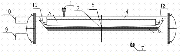
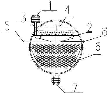
[0014] A condenser with a built-in oil separator, including a condenser body and an oil separator 4, and the oil separator 4 is arranged in the condenser body, and the feature is that: the condenser body is also provided with an oil tank 2 and a pre-cooling The condenser 3, the oil separator 4, the precooler 3 and the oil tank 2 are arranged in the condenser in order from top to bottom, the precooler 3 and the oil separator 4 are seamlessly connected, and the precooler 3 is a fin type The heater and the oil separator 4 are wire mesh oil separators, and the two ends of the precooler 3 are connected with the precooler cooling water inlet 12 and the precooler cooling water outlet 11 arranged on the surface of the condenser body. The bottom of the condenser body is provided with a heat exchange tube bundle ...


PUM


Abstract

The invention discloses a condenser internally provided with an oil separator. The condenser comprises a condenser body and the oil separator. The oil separator is arranged inside the condenser body. The condenser internally provided with the oil separator is characterized in that an oil bath and a precooler are further arranged in the condenser body; the oil separator, the precooler and the oil bath are sequentially arranged in the condenser from top to bottom; the precooler and the oil separator are in seamless connection; a heat exchange device is arranged inside the condenser body; and after entering the condenser through a gas refrigerating fluid inlet in the surface of the condenser, gas refrigerating fluid flows out of the condenser via a liquid-state refrigerating fluid outlet after passing through the oil bath, the precooler, the oil separator and the heat exchange device in sequence. By means of the condenser internally provided with the oil separator, space is saved, cost is low and the oil separation rate is high. By adding the precooling structure, the cooling temperature can be reasonably controlled, refrigerant oil gas in the refrigerating fluid gas can be precipitated into liquid, and thus refrigerant oil can be separated from the refrigerating fluid gas.

Description

technical field [0001] The invention belongs to the refrigeration field, and in particular relates to a condenser with a built-in oil separator. Background technique [0002] In the refrigeration system, the refrigerant gas that participates in the cycle will inevitably be mixed with refrigerating oil, and the refrigerating oil dissolved in the refrigerant will often deposit at the bottom of the evaporator in the form of liquid oil droplets due to the evaporation of the refrigerant, and cannot If the agent gas returns to the crankcase of the compressor, it will easily cause vicious failures such as lack of oil, shaft locking or even burning of the compressor. In addition, when the refrigerated oil enters the evaporator or condenser, a layer of oil film will be formed on the surface of the heat exchange tube, which will reduce the heat transfer coefficient of the heat exchange tube, increase the thermal resistance, reduce the heat exchange efficiency, and affect the performan...

Claims


Application Information

Patent Timeline
Patent Type & Authority Applications(China)
IPC IPC(8): F25B39/04F25B43/02
CPCF25B39/04F25B43/02F25B2500/18F25B2500/05
Inventor 刘焓
Owner 刘焓
Why Eureka
Try Eureka