Wavelength equation parameter particle swarm and extreme value optimization spectrograph wavelength correction method

A technology of parameter optimization and calibration method, which is applied in the direction of spectrometry/spectrophotometry/monochromator, instrument, scientific instrument, etc., and can solve the problems that the wavelength accuracy of the instrument cannot be met and the wavelength scanning error is large.

Inactive Publication Date: 2017-06-27
JILIN UNIV
View PDF4 Cites 8 Cited by
  • Summary
  • Abstract
  • Description
  • Claims
  • Application Information

AI Technical Summary

Problems solved by technology

[0007] The purpose of the present invention is to address the above-mentioned deficiencies in the prior art, to provide a wavelength correction method based on mechanical position error wavelength correction equation parameter optimization, hard adjustment and soft repair, so as to solve the probl

Method used


Image

  • Wavelength equation parameter particle swarm and extreme value optimization spectrograph wavelength correction method
  • Wavelength equation parameter particle swarm and extreme value optimization spectrograph wavelength correction method
  • Wavelength equation parameter particle swarm and extreme value optimization spectrograph wavelength correction method

Examples


Embodiment 1

[0106] Sine scanning spectrometer mechanical position error wavelength correction.

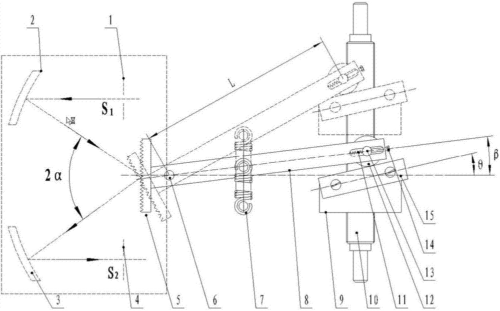
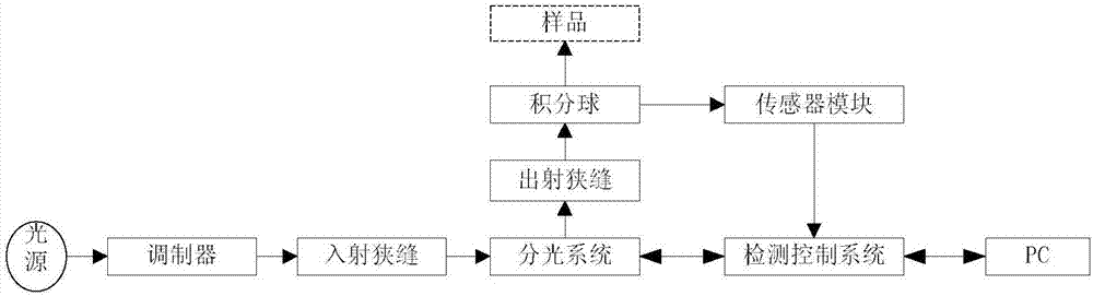
[0107] The structure of the sinusoidal scanning spectrometer is as follows: image 3 As shown, the light source and modulator are fixed outside the incident slit of the spectroscopic system (monochromator), and the relationship between the light source and the incident slit forms an object image, and the detection control system is connected with the spectroscopic system, the sensor module, and the host computer respectively. At the same time, the spectroscopic system is connected with the sensor module through the sampler to form a spectrometer. The structure of the spectroscopic system is as figure 1 A sinusoidal sweep mechanism is shown.

[0108] The implementation process of the correction method for the wavelength error caused by the mechanical position error of the spectroscopic scanning mechanism of the sinusoidal scanning spectrometer is as follows: Figure 4 shown, including the fo...

Embodiment 2

[0137] Sine scanning monochromator mechanical position error correction.

[0138] Build a spectral scanning measurement experimental platform such as Figure 6 As shown, it consists of a standard light source, a spectral scanning control measurement system and a host computer. The standard light source can be a laser, a mercury lamp, etc., which can provide the corresponding standard wavelength within the spectral range of the monochromator, and fix it at the incident slit of the monochromator or spectrometer splitting system, so that the incident light can fill the monochromator or The collimating mirror of the spectrometer's beam splitting system. The spectral scanning control measurement system is located at the exit slit of the monochromator, and controls the stepper motor to rotate the angle continuously at a certain angular interval, so that the monochromator outputs optical signals of different wavelengths at a certain wavelength interval and range; at the same time, t...


PUM


Abstract

The present invention discloses a wavelength equation parameter particle swarm and extreme value optimization spectrograph wavelength correction method. The correction method employs a particle swarm optimization to determine mechanical position error wavelength correction equation parameters, employs extreme value optimization to determine and regulate parameters, and employs hardware regulation and software correction to realize spectrometer wavelength correction. Based on the mechanical position error wavelength equation, two optimization algorithms determine equation parameters, regulate length of the rod and correct a wavelength compensation value so as to perform effective correction of scanning wavelength errors of a raster sine scanning monochromator or a spectrometer. The wavelength equation parameter particle swarm and extreme value optimization spectrograph wavelength correction method solves the problems that the wavelength scanning error of a monochromator rester scanning mechanism is big and cannot satisfy the wavelength precision of a device caused by optical zero position errors and roller guidance errors, and solves the problem that the wavelength equation parameters cannot be solved. The method combines software and hardware, is easy to operate, does not need to perform calculation processing of spectrum data of an instrument every time, and is suitable for wavelength correction when monochromator or spectrometer products are checked and debugged.

Description

technical field [0001] The invention relates to a method for correcting the scanning wavelength error caused by the scanning mechanical position error of a spectrometer, in particular to a method for correcting the wavelength error of a grating sinusoidal scanning monochromator or spectrometer. Background technique [0002] The wavelength scanning of the grating scanning spectrometer adopts a sinusoidal transmission mechanism. The stepping motor drives the screw to rotate and the nut to move. Shade. [0003] There are optical zero position error and pendulum roller guide error in the assembly process of this raster scanning mechanism. [0004] The optical zero position refers to the position where the spectrometer outputs zero-order light. At this time, the normal line of the plane grating coincides with the bisector of the angle between the incident light and the diffracted light of the spectroscopic system (hereinafter referred to as the bisector of the spectroscopic lin...

Claims


Application Information

Patent Timeline
IPC IPC(8): G01J3/28
CPCG01J3/28G01J2003/2879
Inventor 王智宏刘杰陈琛千承辉于永
Owner JILIN UNIV
Why Eureka
Try Eureka