Backlight module detection equipment and detection method

A backlight module and detection equipment technology, which is applied in optical instrument testing, machine/structural component testing, measuring devices, etc., can solve problems such as backlight module detection errors, unqualified product missed inspections, and prone to errors, etc., to achieve The effect of improving detection efficiency and reducing missed detection, reducing manual labor and production costs

Active Publication Date: 2017-06-27
SHENZHEN TECHASER TECH
View PDF6 Cites 36 Cited by
  • Summary
  • Abstract
  • Description
  • Claims
  • Application Information

AI Technical Summary

Problems solved by technology

In the process of traditional backlight module processing, it is usually necessary to detect from different angles whether there are black and white spots and color differences inside the product, whether there are scratches and dust on the appearance, and in this inspection process, the operation fineness of the backlight module to be inspected Higher requirements are put forward. Usually, the internal and external p

Method used


Image

  • Backlight module detection equipment and detection method
  • Backlight module detection equipment and detection method
  • Backlight module detection equipment and detection method

Examples


Embodiment Construction

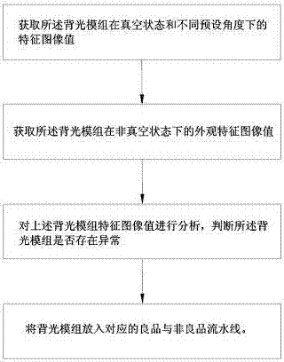
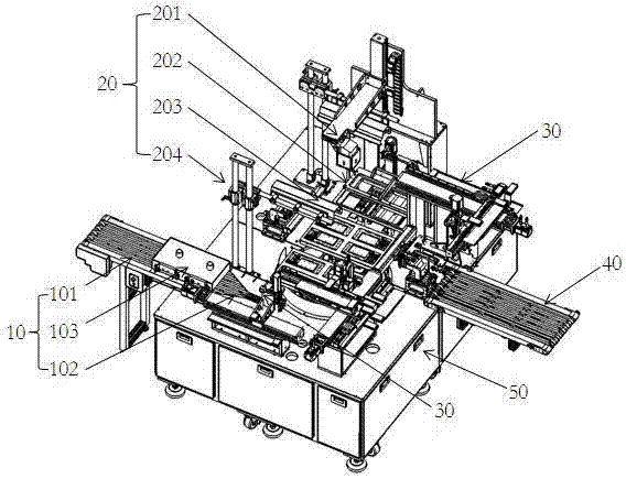
[0039] The present invention as figure 1 As shown, a detection device for a backlight module includes:

[0040] The feeding assembly line 10, the feeding assembly line 10 includes a feeding track 101, an incoming material sensor 102 and a dust removal device 103, the dust removal device 103 is located in the middle section of the feeding line 10, and the dust removal device 103 is sucked onto the feeding track 101 by ion wind blowing and a blower The backlight module is used for dust removal, and the incoming material sensor 102 is fixed at the end of the feeding track 101 in the conveying direction.

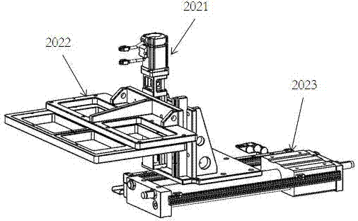
[0041] The detection machine 20 is located on one side of the feeding line 10, and includes a CCD detection device 201, a vacuum module 202, a detection station 203, and a light source 204. The CCD detection device 201 and the light source 204 are arranged above the detection station 203, and the vacuum module 202 and the detection station 203 are all fixed on the detection mac...


PUM


Abstract

The invention discloses backlight module detection equipment and a backlight module detection method. The detection equipment comprises feeding production lines, a detection station, a manipulator and qualified and non-qualified production lines, wherein the feeding production lines used for providing to-be-detected backlight modules to the detection station, the detection station is arranged at one side of a material supply track and comprises a CCD detection device, a light source, a vacuum assembly and a detection work station, the vacuum assembly and the detection work station are fixed on the detection station, during operation, through arranging the CCD detection device, the vacuum module and a turning rotation disc, internal and external portions of the backlight modules are sequentially detected, after analysis on characteristic image values of the backlight modules is carried out through the CCD detection device, whether abnormality exists is determined, and the backlight modules can be disposed by a background control system through the manipulator to the corresponding qualified and non-qualified production lines. The detection equipment is advantaged in that internal and external detection on the backlight modules can be realized automatically, so whether the backlight modules are abnormal can be determined, detection efficiency is improved, a problem of easily-generated errors because of manual detection can be avoided, manpower cost is reduced, and production quality is improved.

Description

technical field [0001] The invention relates to the field of display technology, in particular to a detection device for a backlight module and a detection method thereof. Background technique [0002] On intelligent automation equipment, automation equipment or image detection technology is often used for product quality inspection. Using image positioning or image detection technology will inevitably use a camera, that is, a CCD detection device. In these high-precision intelligent applications, CCD The detection device must be fixed in some specific positions of the equipment in order to capture a clear and effective image. In the process of traditional backlight module processing, it is usually necessary to detect from different angles whether there are black and white spots and color differences inside the product, whether there are scratches and dust on the appearance, and in this inspection process, the operation fineness of the backlight module to be inspected Highe...

Claims


Application Information

Patent Timeline
IPC IPC(8): G01M11/02G01N21/892
CPCG01M11/00G01N21/892G01N2021/8925
Inventor 杨威
Owner SHENZHEN TECHASER TECH
Why Eureka
Try Eureka