
Catalyst testing system

A test system and catalyst technology, which is applied in the field of catalyst test systems, can solve problems such as dead volume, poor separation effect, and gas-liquid mixing affecting test results, etc., to achieve the effect of preventing condensation and good test results

Inactive Publication Date: 2017-06-27
天津神能科技有限公司
View PDF0 Cites 2 Cited by
  • Summary
  • Abstract
  • Description
  • Claims
  • Application Information

AI Technical Summary

Problems solved by technology

[0003] The present invention provides a catalyst test system to solve the problems in the above-mentioned background technology that it is easy to generate dead volume, the separation effect is not good, and it is easy to cause gas-liquid mixing before entering the detector to affect the effect of the test.

Method used


Image

  • Catalyst testing system

Examples


Embodiment Construction

[0016] The present invention will be further described below in conjunction with accompanying drawing:

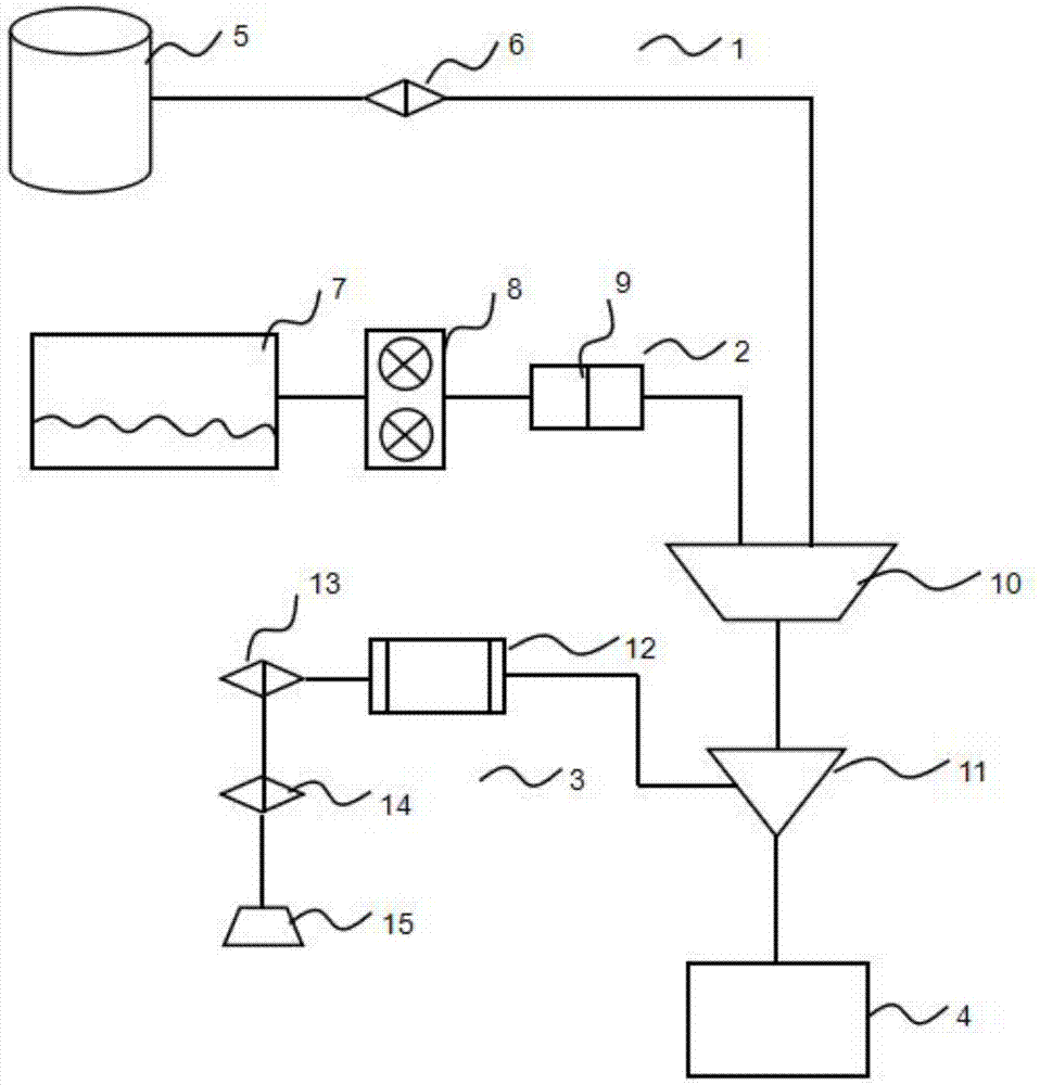
[0017] This embodiment: as figure 1 As shown, the catalyst test system includes a gas supply device 1, a sample injection device 2, a separation reaction device 3, and a liquid sample detector 4, and the gas supply device 1 includes a rigid gas storage tank 5 and a gas supply flowmeter 6. The sampling device 2 includes a liquid storage tank 7, a flow pump 8, and a preheater 9, and the separation reaction device 3 includes a reactor 10, a condenser 11, a gas-liquid separator 12, a separation flowmeter 13, a gas flowmeter 14, Outlet valve 15.

[0018] The gas supply device 1 and the sampling device 2 are respectively connected to the separation reaction device 3, the separation reaction device 3 is connected to the liquid sample detector 4, and the rigid gas storage tank 5 is connected to the reactor through the gas supply flow meter 6 10. The liquid storage tank 7 is conne...


PUM


Abstract

The invention belongs to the technical field of chemical testing, and particularly relates to a catalyst testing system, which includes a gas supply device, a sample feeding device, a separation reaction device, and a liquid sample detector. Before entering the detector, it is easy to cause the problem of gas-liquid mixing affecting the test effect. It has the beneficial technical effects of good test effect, prevention of condensation, avoiding dead volume, precise control of water content in the gas, and less water content of the sample after separation.

Description

technical field [0001] The invention belongs to the technical field of chemical testing, in particular to a catalyst testing system. Background technique [0002] At present, the micro-reaction system simulates the environment used by the catalyst, or adjusts the process parameters and reaction atmosphere according to the needs of the experimenter, and evaluates the performance of the catalyst. Widely involved in the fields of environmental protection, chemical industry and functional materials, including: vehicle exhaust purification, fixed source denitrification, VOC catalytic combustion, catalytic hydrogenation and the development of various functional adsorption materials, etc., the catalyst loading volume that can be evaluated is 1-1000ml, Catalyst forms include granular, honeycomb, etc. The existing technology has the problems of easy to produce dead volume, poor separation effect, and easy to cause gas-liquid mixing before entering the detector to affect the effect of...

Claims


Application Information

Patent Timeline
Patent Type & Authority Applications(China)
IPC IPC(8): G01N33/00G01N35/10
CPCG01N33/00G01N35/10
Inventor 刘雁王震宇王宝义
Owner 天津神能科技有限公司
Learn More