
A digitally controlled brick pushing device and method for an edge grinder

A technology of edging machine and brick pushing mechanism, which is applied in the direction of computer control, program control, general control system, etc., can solve the problems of personal safety accidents, damage of brick pushing mechanism, poor precision, etc., and achieve strong market promotion prospects, Save labor costs and have strong practicability

Active Publication Date: 2019-05-21
KEDA INDUSTRIAL GROUP CO LTD
View PDF6 Cites 0 Cited by
  • Summary
  • Abstract
  • Description
  • Claims
  • Application Information

AI Technical Summary

Problems solved by technology

At present, the position of the brick pushing claw of the edger is manually adjusted, and the operator adjusts the fixing screw of the brick pushing claw through a tool. This adjustment method is not only extremely inconvenient, but also prone to personal safety accidents
In addition, when the diagonal error of the brick grinding product is too large, it is necessary to manually adjust the position of the brick pushing claw for many times. Since the manual adjustment accuracy is not digitally quantified, the accuracy of the adjustment is poor, and there is a slight difference, which will also cause the brick pushing mechanism. Problems with damaged or ground brick products

Method used


Image

  • A digitally controlled brick pushing device and method for an edge grinder
  • A digitally controlled brick pushing device and method for an edge grinder
  • A digitally controlled brick pushing device and method for an edge grinder

Examples


Embodiment Construction

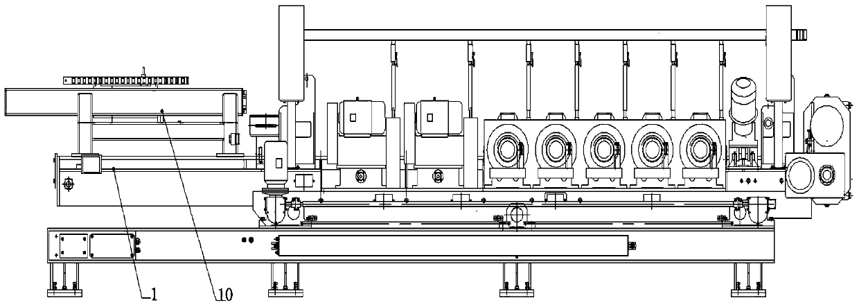
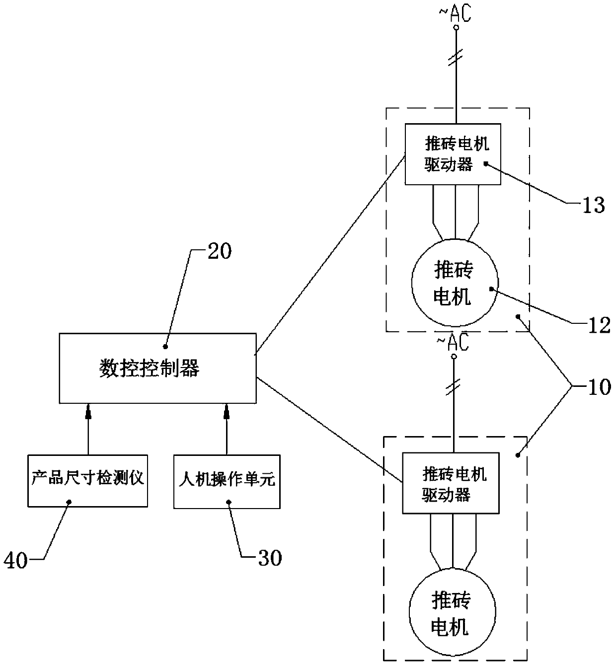
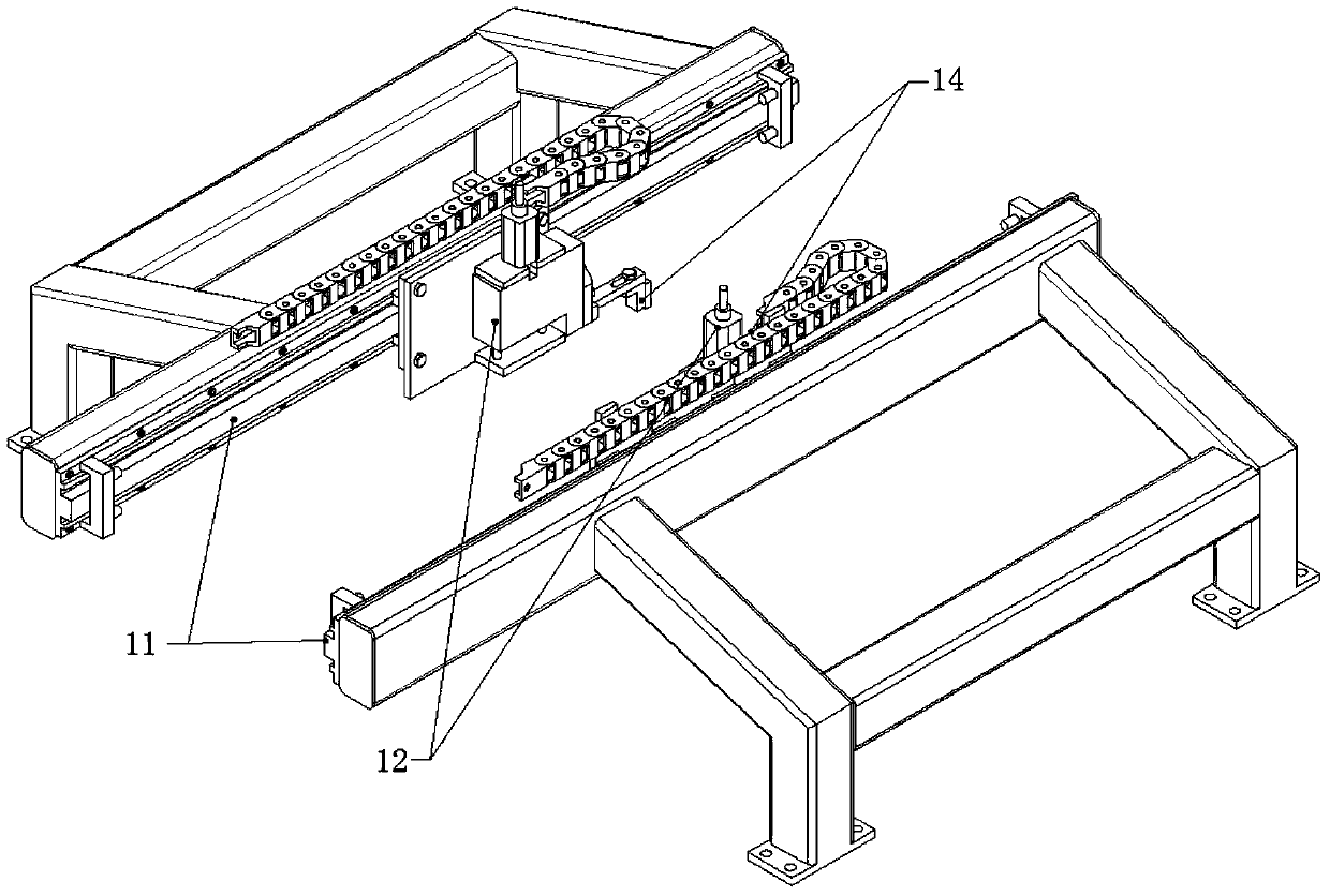
[0030] see Figure 1-Figure 4 . figure 1 It is a schematic diagram of the installation position of the brick pushing mechanism. figure 2 It is a schematic diagram of the connection relationship of the CNC brick pushing device of the edging machine. image 3 It is a structural schematic diagram of the brick pushing motor and the brick pushing claw. Figure 4 It is a schematic diagram of the position of brick pushing claws and brick grinding products. The invention provides a numerically controlled brick pushing device for an edge grinder, comprising

[0031] --Brick pusher mechanism 10, described brick pusher mechanism 10 is arranged on the frame of edging machine 1, described brick pusher mechanism 10 comprises two linear guide rails 11, each is provided with a brick pusher motor 12 on described linear guide rail 11 , the brick pushing motors 12 are respectively connected with a brick pushing motor driver 13, the brick pushing motors 11 drive the brick pushing claws 14 fi...


PUM


Abstract

The invention discloses a numerical-control brick piling device and method for an edge grinding machine, and the device comprises a brick piling mechanism, and the brick piling mechanism is disposed on the rack of the edge grinding machine. The brick piling mechanism comprises two straight guide rails, and the straight guide rails are respectively provided with a brick piling motor. The brick piling motors are respectively connected with a brick piling motor driver, and the brick piling motors drive brick piling claws fixedly connected with the brick piling motors. The device also comprises a numerical controller which is disposed on the brick piling mechanism and is in communication connection with the brick piling motor drivers; a man-machine operation unit which is in communication connection with a communication interface of the numerical controller; and a product size detector which is in communication connection with the communication interface of the numerical controller. The device solves technical problems that a conventional edge grinding machine needs to manually and mechanically adjust the position of the brick piling claws, the personal safety affected by the above problem cannot be guaranteed and the precision is poor.

Description

technical field [0001] The invention relates to the field of building materials machinery, in particular to a digitally controlled brick pushing device and method for an edge grinder. Background technique [0002] Edge grinding machine is a relatively commonly used equipment in the field of building materials. For example, ceramic materials, glass materials, marble materials and other brick-shaped building materials need to be processed by edge grinding machines. The brick pushing claw of the traditional edging machine is the key part responsible for controlling the diagonal error of the grinding brick product. At present, the position of the brick pushing claw of the edger is manually adjusted, and the operator adjusts the fixing screw of the brick pushing claw through a tool. This adjustment method is not only extremely inconvenient, but also Personal safety accidents are prone to occur. In addition, when the diagonal error of the brick grinding product is too large, it ...

Claims


Application Information

Patent Timeline
Patent Type & Authority Patents(China)
IPC IPC(8): G05B19/409
CPCG05B19/409
Inventor 詹新平
Owner KEDA INDUSTRIAL GROUP CO LTD
Learn More