
Temperature control mechanism for electronic component bonding device, method and test equipment provided with same

A technology of electronic components and temperature control mechanism, which is applied to auxiliary controllers with auxiliary heating devices, temperature control and measuring devices using electric methods, and can solve the problems of inability to provide, increase test time, and inability to use different batches of electronic components Test and other issues

Active Publication Date: 2017-06-27
HON PRECISION INC
View PDF11 Cites 4 Cited by
  • Summary
  • Abstract
  • Description
  • Claims
  • Application Information

AI Technical Summary

Problems solved by technology

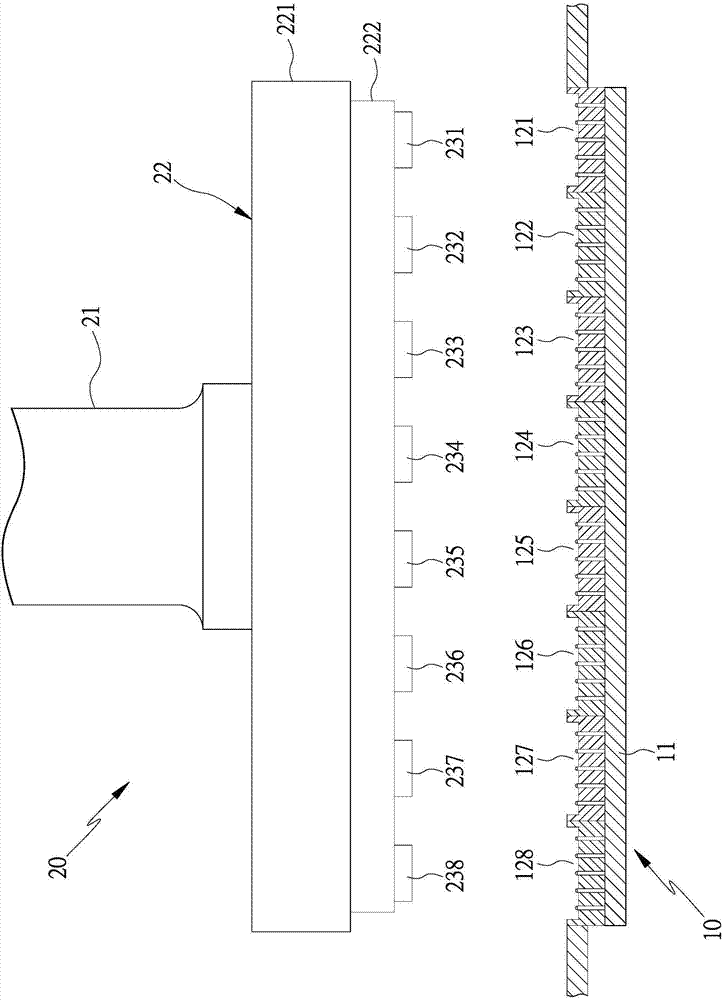
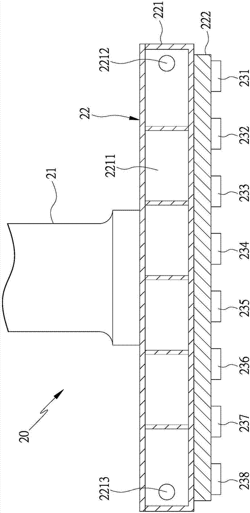
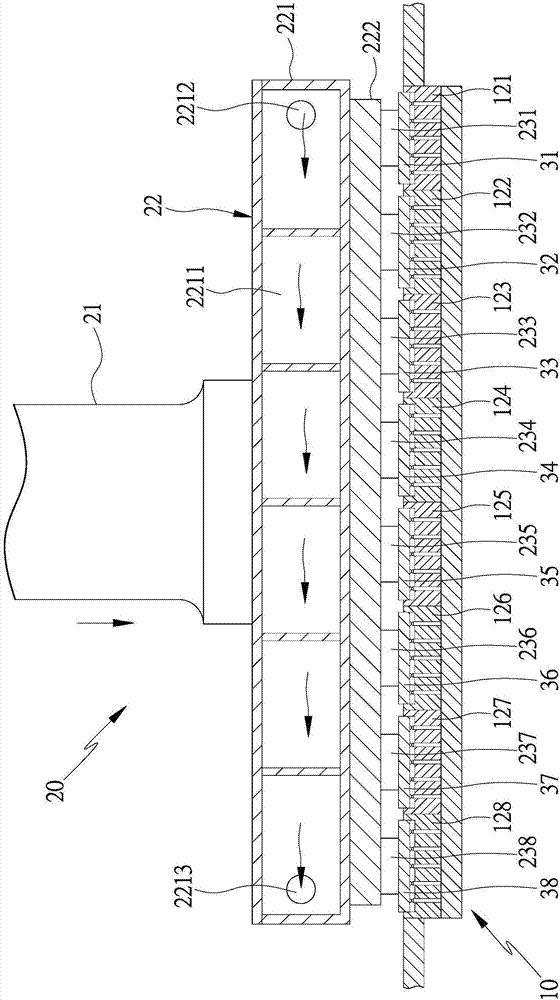
[0004] 1. When the multiple crimpers 231, 232, 233, 234, 235, 236, 237, 238 of the crimping device 20 are to be used to crimp multiple electronic components 31, 32, 33 of the same batch at the same preset test temperature , 34, 35, 36, 37, and 38 when testing, because the refrigerant in the cooler 221 flows in the flow channel 2211, it will gradually heat up due to the exchange of cold and heat, causing different parts of the bottom surface of the cooler 221 to have different low temperatures, such as the front end The position is -30 degrees low temperature, the middle part is -20 degrees low temperature, and the rear end is -10 degrees low temperature. The temperature of different parts provides different high temperatures for collocation and integration, so that multiple crimpers 231, 232, 233, 234, 235, 236, 237, 238 crimp multiple electronic components 31, 32, 33 of the same batch at different low temperatures , 34, 35, 36, 37, 38 for testing, resulting in different test quality of multiple electronic components
[0005] 2. Due to the different batches of multiple electronic components, their preset test temperatures are also different. When two different preset test temperatures are used to crimp two different batches of multiple electronic components for testing, since different parts of the cooler 221 have different low temperatures, and only a single high temperature of a heater is used for temperature integration, so that 8 Crimpers 231, 232, 233, 234, 235, 236, 237, and 238 were tested with eight different low-temperature crimps for two batches of multiple electronic components, and it was impossible to make multiple electronic components of the same batch in the same batch. test at a preset test temperature, and it is impossible to test another batch of electronic components at another preset test temperature, so that the crimping device 20 cannot test different batches of electronic components at one time, but must be divided into different batches of electronic components. Testing in batches not only fails to increase the testing capacity, but also increases the testing time

Method used


Image

  • Temperature control mechanism for electronic component bonding device, method and test equipment provided with same
  • Temperature control mechanism for electronic component bonding device, method and test equipment provided with same
  • Temperature control mechanism for electronic component bonding device, method and test equipment provided with same

Examples


Embodiment Construction

[0042] In order for the examiner to have a further understanding of the present invention, a preferred embodiment is hereby given together with the drawings, and the details are as follows:

[0043] like Figure 4 , Figure 5 As shown, the joint device 40 in the present invention is provided with a moving arm 41 that moves in at least one direction. In this embodiment, the moving arm 41 is driven by a driving source (not shown) to move in the Z direction, and the joint The device 40 is equipped with a temperature control mechanism 42 below the moving arm 41. The temperature control mechanism 42 is provided with a cooling module 421 with a cold source. The cold source can be a cryogenic fluid (such as a refrigerant) or a cooling chip. In this embodiment Among them, the cooling module 421 is installed under the moving arm 41, and an S-shaped flow channel 4211 is provided inside. One end of the flow channel 4211 is connected to a fluid input pipe 4212 that can input low-temperat...


PUM


Abstract

The invention discloses a temperature control mechanism for an electronic element bonding device and a temperature control method. The temperature control mechanism for the electronic component bonding device is provided with a temperature control mechanism to drive by the mobile arm moving in at least one direction, a cooling module is provided with a temperature control mechanism of the cold source, and beneath the cooling module assembly of a plurality of heating the module with a heat source, a plurality of heating module assembly has a plurality of adapter, and the adapter contacted by contact with electronic components, a plurality of heating module equipped with a temperature sensing module, a temperature sensing module temperature data to the controller, controller of multiple temperature data to judge, to determine how a heating module meets the preset test temperature range, output power and real-time control compensation multiple heating module, multiple heating module temperature to meet the preset temperature range, and the plurality of adapter to test the preset temperature contact electronic components and test to improve the test quality and production efficiency.

Description

technical field [0001] The invention relates to a real-time regulation and compensation of the output power of multiple heating modules according to the temperature of different parts of the cooling module, so that multiple adapters can contact electronic components at a preset test temperature for testing, and can be used according to different batches of electronic components The test temperature requirements set multiple heating modules to the same or different test temperatures, so as to simultaneously test different batches of electronic components, thereby improving the test quality and production efficiency of the temperature control mechanism of the electronic component bonding device. Background technique [0002] At present, when testing electronic components, the crimping device of the crimping device is generally used to press the electronic components, and the temperature control mechanism is used to test the electronic components within the preset test temperatu...

Claims


Application Information

Patent Timeline
Patent Type & Authority Applications(China)
IPC IPC(8): G05D23/32G01R31/00
CPCG01R31/003G05D23/32
Inventor 林正龙
Owner HON PRECISION INC
Learn More