Bionic type artificial intervertebral disc and forming method thereof

A kind of intervertebral disc and bionic technology, applied in medical science, spinal implants, prostheses, etc., can solve problems such as lack of elasticity, influence of surrounding tissues, interface problems, etc., to avoid interface separation, achieve stability, avoid The effect of side effects

Active Publication Date: 2017-06-30
BEIJING UNIV OF CHEM TECH
View PDF11 Cites 12 Cited by
  • Summary
  • Abstract
  • Description
  • Claims
  • Application Information

AI Technical Summary

Problems solved by technology

On the one hand, this kind of hard-supported ball-and-socket structure is not elastic, and cannot protect the cervical spine well when it is shaken; organizations that have an impact on
The C-type prosthesis does not contain articular surfaces, and its mobility is mainly achieved through the elastic deformation of the nucleus pulposus material. This type of prosthesis also includes a load attenuation function, but there are still a large number of interfaces between the nucleus pulposus and the endplate, as disclosed in the patent US8377138B2 A C-shaped prosthesis, which fixedly connects the elastomeric nucleus pulposus material to the rigid endplate through traditional mechanical fitting and other connection methods. Although a certain connection has been achieved, the elastomeric nucleus pulposus material and the metal rigid endplate The plate will have interface problems, and there will also be a displacement interface between the endplate components. During the long-term use of the implant in the body, problems such as material wear, heat generation, and shedding may still occur due to repeated friction

Method used


Image

  • Bionic type artificial intervertebral disc and forming method thereof
  • Bionic type artificial intervertebral disc and forming method thereof
  • Bionic type artificial intervertebral disc and forming method thereof

Examples


Embodiment Construction

[0022] The present invention will be further described below in conjunction with the accompanying drawings.

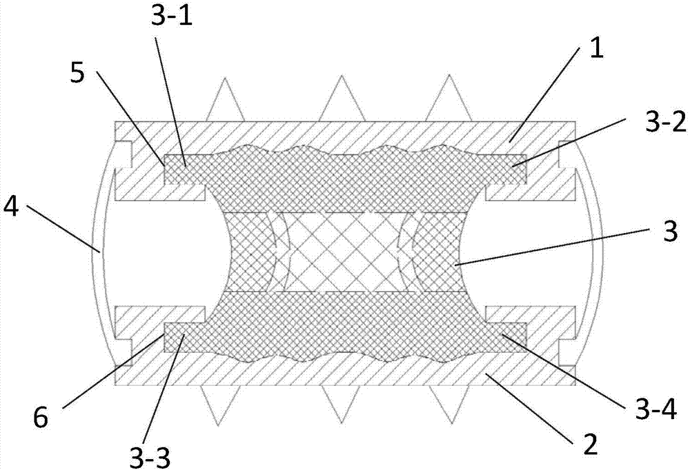
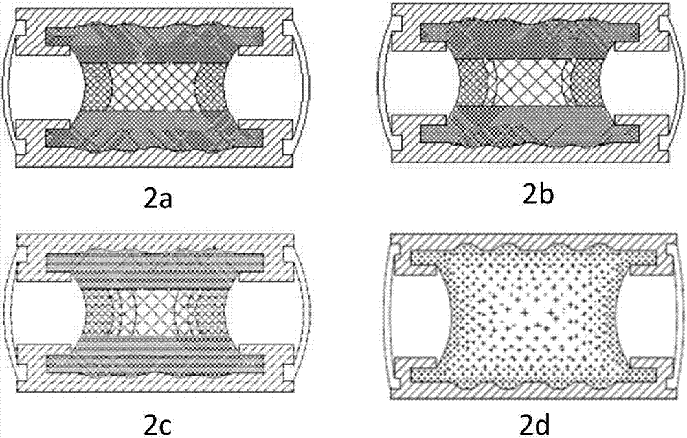
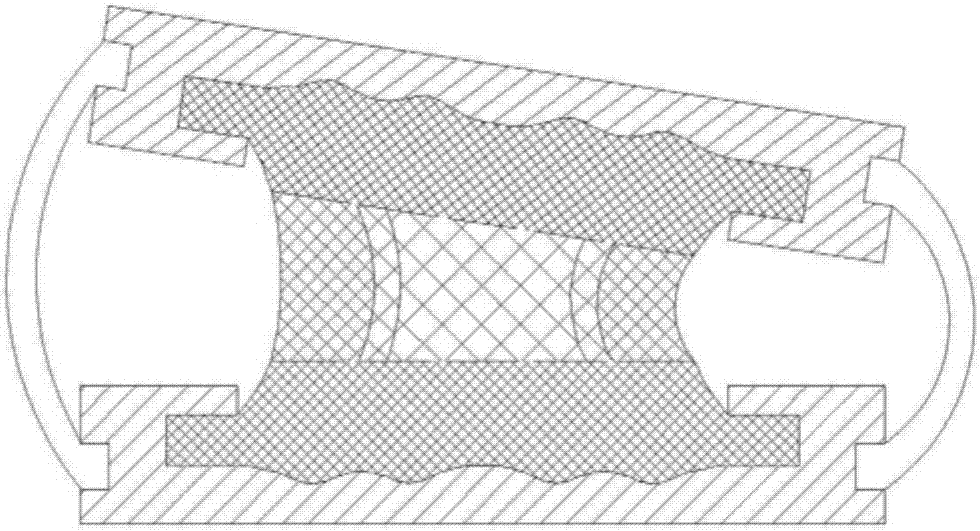
[0023] Such as figure 1 As shown, a bionic artificial intervertebral disc consists of an upper rigid endplate 1, a lower rigid endplate 2, an elastic nucleus pulposus 3 arranged between the upper rigid endplate 1 and the lower rigid endplate 2, and an elastic nucleus pulposus 3 arranged outside the elastic nucleus pulposus 3. The elastic nucleus pulposus 3 is composed of two or more polyurethane materials with different elastic moduli, and the polyurethane materials with different elastic moduli are connected as a whole. The elastic nucleus pulposus 3 is connected with the upper rigid endplate 1 and the lower rigid endplate. The end plate 2 is integrally formed without a friction interface, and the elastic modulus of the material on both sides of the elastic nucleus pulposus 3 is higher than that at the center of the elastic nucleus pulposus. The first extension part ...


PUM

PropertyMeasurementUnit
elastic modulusaaaaaaaaaa

Abstract

The invention relates to a bionic type artificial intervertebral disc and a forming method thereof. The bionic type artificial intervertebral disc is composed of an upper rigid end plate, a lower rigid end plate, an elastic nucleus pulposus arranged between the upper rigid end plate and the lower rigid end plate and a film body arranged at the outer side of the elastic nucleus pulposus; the elastic nucleus pulposus is constituted by adopting two or more polyurethane materials with different elasticity moduli, and the polyurethane materials with the different elasticity moduli are integrally connected. When the bionic type artificial intervertebral disc is molded, the center of the nucleus pulposus is firstly formed to connect the upper rigid end plate-polyurethane material workpiece and the lower rigid end plate-polyurethane material workpiece, and then the outer side is injected with the polyurethane materials. The bionic type artificial intervertebral disc is of an integral structure, and when the bionic type artificial intervertebral disc is loaded, through elastic deformation of the elastic nucleus pulposus, physiological activities of the artificial intervertebral disc in all directions are achieved.

Description

technical field [0001] The invention relates to a bionic artificial intervertebral disc and a molding method thereof, and to the technical field of medical implantable orthopedic medical devices. Background technique [0002] The intervertebral disc is the main component of the spinal motion segment. Its main function is to produce special limited activities between two adjacent vertebral bodies, absorb and buffer shocks with the help of the elasticity of the nucleus pulposus and the special structure of the fibrous annulus. Since the launch of the first generation of intervertebral disc prosthesis - ball joint prosthesis, ball and socket prosthesis, arch prosthesis, articular disc prosthesis and hard endplate-hard nucleus prosthesis have been developed successively, which can better meet the The prosthesis required by human biomechanics, however, most of these prostheses basically give up the requirement for elasticity, and focus on motion retention. Other prostheses desig...

Claims


Application Information

Patent Timeline
Patent Type & Authority Applications(China)
IPC IPC(8): A61F2/44
CPCA61F2/442A61F2002/443A61F2220/0016A61F2220/0033A61F2240/002A61F2310/00407A61F2310/00796
Inventor 孟阳冯巧芳姜秀娟张立群
Owner BEIJING UNIV OF CHEM TECH
Why Eureka
Try Eureka