Grinding machine flue gas purifying method

A flue gas purification and flue gas technology, which is applied in the field of flue gas purification, can solve problems such as troublesome, large amount of engineering, and inconvenient implementation

Inactive Publication Date: 2017-06-30
SUZHOU YASIKE PRECISION CNC CO LTD
View PDF7 Cites 3 Cited by
  • Summary
  • Abstract
  • Description
  • Claims
  • Application Information

AI Technical Summary

Problems solved by technology

This patent needs to arrange a complete pipeline system, which is not suitable for use in grinding machine workshops. When the position of the grinding machine equipment needs

Method used


Image

  • Grinding machine flue gas purifying method

Examples


Embodiment Construction

[0024] The present invention will be further explained below in conjunction with the accompanying drawings and specific embodiments. It should be understood that the following specific embodiments are only used to illustrate the present invention but not to limit the scope of the present invention.

[0025] The flue gas purification method of the grinder comprises the following steps:

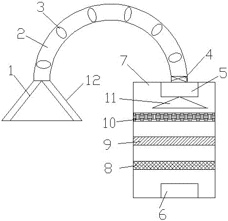
[0026] Step 1: Assemble the flue gas purifier: figure 1 It is a structural schematic diagram of the present invention. It can be seen from the accompanying drawings that the flue gas purifier includes a dust suction hood 12, a flue and a purification box 7. Several filter elements 3 are arranged in the flue gas pipe 2 of the flue gas purifier. The outlet end of 2 is provided with wind speed sensor 4;

[0027] Step 2: Adhesive removal of flying dust particles in the flue gas: the flying dust generated by the grinder passes through the dust suction hood 12 of the flue gas purifier, and the flyi...


PUM


Abstract

The invention discloses a grinding machine flue gas purifying method. The flue gas purifying method comprises the following steps: 1) assembling a flue gas purifier; 2) removing dust particles in the flue gas through gluing; 3) filtering the particles in the flue gas; 4) dispersing wind speed; 5) filtering the particles in the flue gas; 6) removing smell in the flue gas; and 7) discharging clean gas. The gas purifying method can remove the dust and polluted gas during a polishing process by a grinding machine, can avoid the diffusion of dust and polluted gas in a workshop, and can protect the workshop environment.

Description

technical field [0001] The invention relates to a flue gas purification method for a grinder, and belongs to the technical field of flue gas purification. Background technique [0002] The smoke and dust purifier is a high-efficiency air purifier designed for industrial waste gas, smoke and dust. Air purification system. Widely used in machinery, hardware, electronic appliances, optoelectronics, chemicals, tobacco, pharmaceuticals, food, biology and other industries and other places polluted by smoke, smoke and dust. [0003] After searching, the inventor found that the patent number is: 201610111526.6, and the patent name is: flue gas purification method and flue gas purification equipment. The patent discloses: a flue gas purification method includes the following steps: increasing the cross-sectional area of ​​flue gas, reducing Part of the gas and smoke are separated naturally; the smoke is passed through the smoke filter to separate the gas and smoke in the smoke; wat...

Claims


Application Information

Patent Timeline
IPC IPC(8): B01D46/00B01D53/04
CPCB01D46/0027B01D46/0038B01D53/04B01D2267/40B01D46/62
Inventor 马峻薛松孙建明
Owner SUZHOU YASIKE PRECISION CNC CO LTD
Why Eureka
Try Eureka