Workpiece auto-collimation method and system in laser engraving

A laser engraving and self-aligning technology, applied in laser welding equipment, manufacturing tools, metal processing equipment, etc., can solve the problems of low work efficiency, slow debugging speed, etc., to improve quality, convenient and accurate debugging of position, improve The effect of overall productivity and alignment accuracy

Active Publication Date: 2017-06-30
浙江创新激光设备有限公司
View PDF8 Cites 6 Cited by
  • Summary
  • Abstract
  • Description
  • Claims
  • Application Information

AI Technical Summary

Problems solved by technology

The entire position adjustment process is manually adjusted, and the debugging speed is slow. For batch laser engraving production, the work efficiency is low

Method used


Image

  • Workpiece auto-collimation method and system in laser engraving
  • Workpiece auto-collimation method and system in laser engraving
  • Workpiece auto-collimation method and system in laser engraving

Examples


Embodiment 1

[0041] Embodiment one, such as Figure 5 As shown, a self-alignment method for workpieces in laser engraving, the method includes:

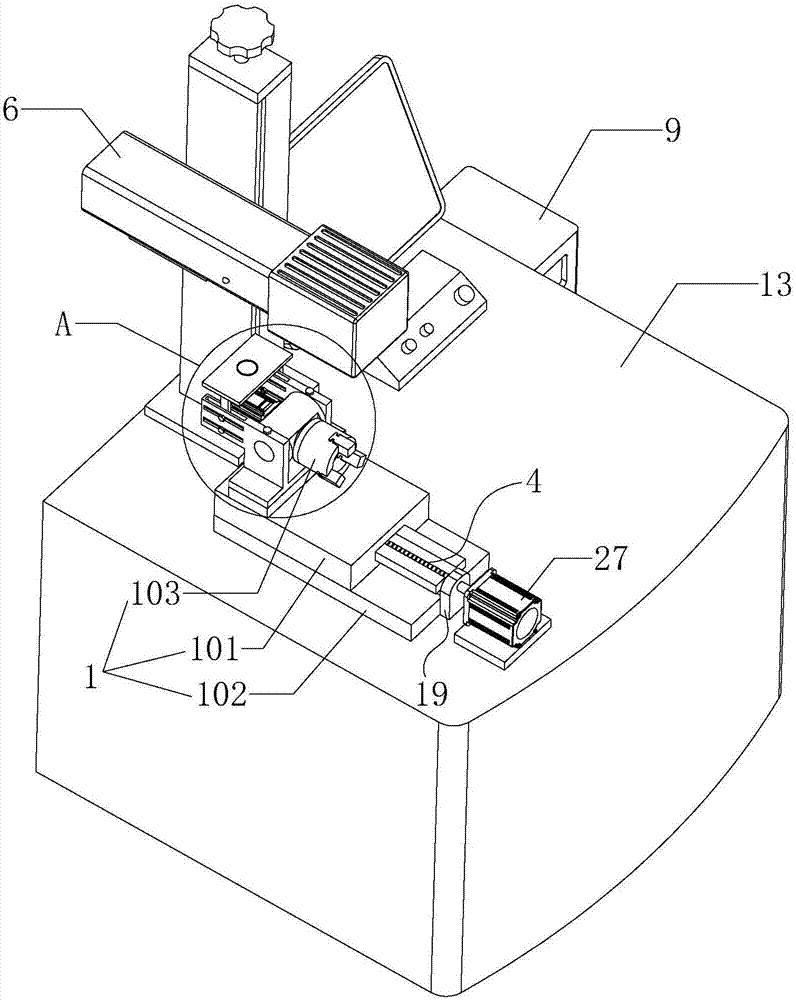
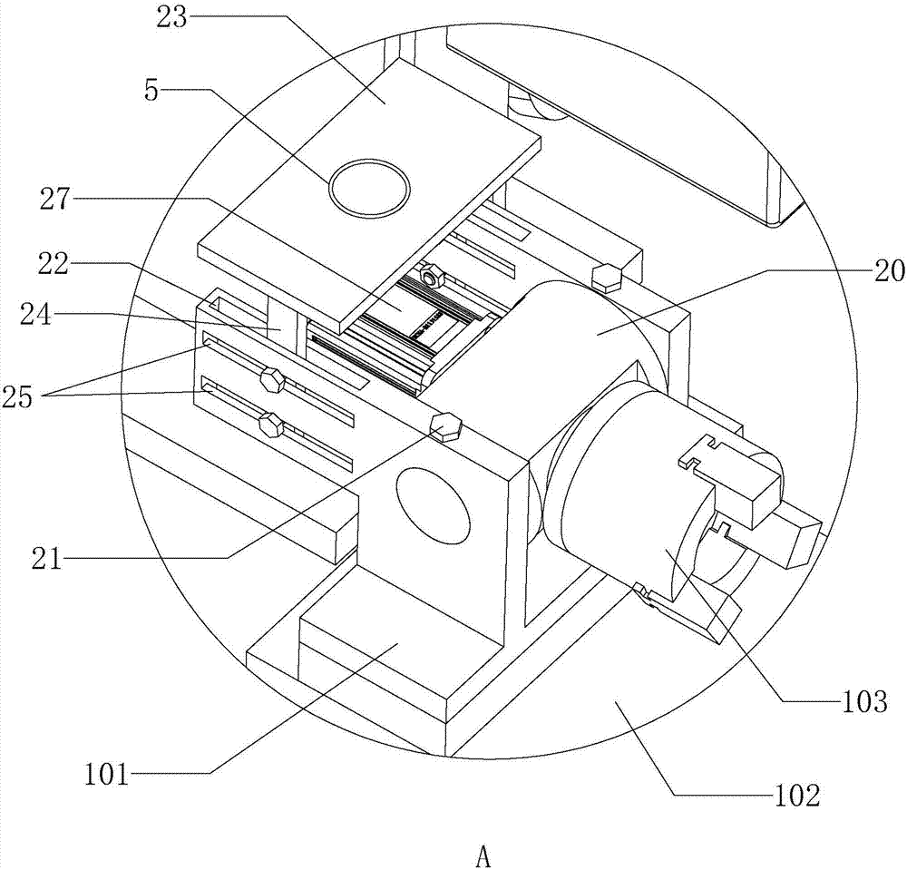
[0042] Step S1: if figure 1 As shown, the rotating base 101 is screwed to the screw 4 on the sliding base 102 in advance, and the two sides of the rotating base 101 are slid and clamped on the sliding base 102 along the length direction of the screw 4 (this step is initially It is completed when the mounting base 1 is installed on the working platform 13, and the subsequent replacement of the fixture 103 generally does not need to be repeated, which is not shown in the drawings);

[0043] Step S2: fixing the workpiece on the fixture 103 of the rotating base 101;

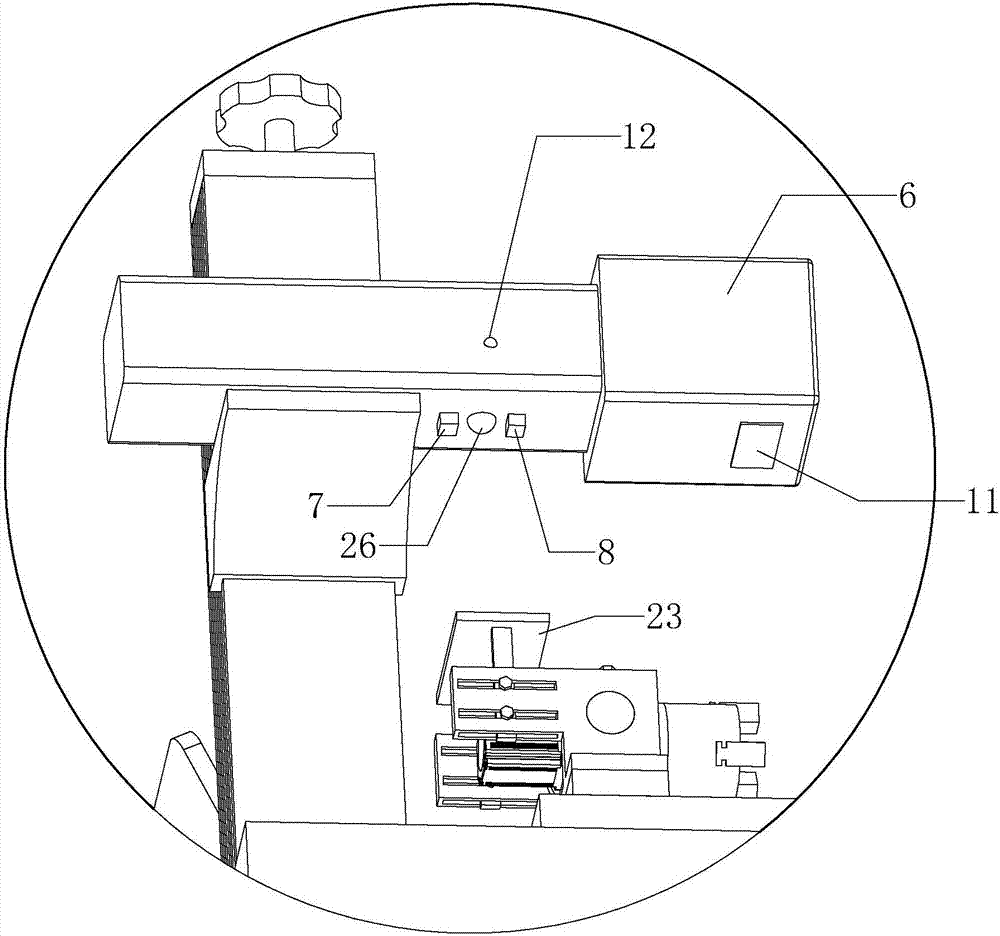
[0044] Step S3: if figure 1 , figure 2 and image 3 As shown, the electromagnetic field is emitted upward by rotating the electromagnetic field emitting coil 5 with alternating current on the base 101, and then passes through the first magnetic field sensor 7 and the second magnet...

Embodiment 2

[0054] Embodiment two, such as figure 1 As shown, a self-alignment system for workpieces in laser engraving includes a working platform 13 , a mounting base 1 fixed on the working platform 13 , and a dynamic focusing laser galvanometer module 6 arranged above the mounting base 1 .

[0055] Such as figure 1 and Figure 4 As shown, a vertical lifting frame 14 with a cavity inside is fixed on the working platform 13, and a vertical screw rod 15 is rotatably connected in the lifting frame 14. A rotating handle 16 is fixed on the top of the lifting frame 14 and the top of the screw rod 15 . The side wall of lifting frame 14 has vertical groove 17, and dynamic focusing laser vibrating mirror module 6 is fixed on a lifting platform 18, and lifting platform 18 passes through vertical groove 17 and is threadedly connected with screw rod 15. By rotating the rotary handle 16 at the top of the screw rod 15, the lifting platform 18 can be lifted along the length direction of the screw r...


PUM


Abstract

The invention discloses a workpiece auto-collimation method and system in laser engraving. The method includes the steps that an electromagnetic field transmitting coil on a base is rotated to upwards transmit an electromagnetic field, a first magnetic field sensor and a second magnetic field sensor which are arranged on a dynamic convergence laser galvanometer module in a spaced manner in the length direction of a lead screw are used for detecting the electromagnetic field strength; a controller controls starting and stopping of a first servo motor and the rotating direction of an output shaft according to detecting signals output by the first magnetic field sensor and the second magnetic field sensor; when the electromagnetic field strength detected by the first magnetic field sensor and the second magnetic field sensor is larger than a preset value, the controller controls the first servo motor to stop rotating, automatic collimation of a workpiece and a protection window of the dynamic convergence laser galvanometer module is achieved; and the beneficial effect of greatly improving the laser engraving overall working efficiency and the collimation accuracy is achieved.

Description

technical field [0001] The invention relates to laser processing technology, more specifically, it relates to a method and system for self-alignment of workpieces in laser engraving. Background technique [0002] Laser engraving is based on numerical control technology, and laser is the processing medium. The physical denaturation of the instant melting and gasification of the processed material under laser irradiation achieves the purpose of processing. Laser processing has no contact with the surface of the material, is not affected by mechanical movement, the surface will not deform, and generally does not need to be fixed. Not affected by the elasticity and flexibility of the material, it is convenient for soft materials. High processing precision, fast speed, wide range of applications. [0003] The Chinese patent with publication number CN105974581A discloses that the present invention relates to a high-speed dynamic focusing laser galvanometer module. Its purpose ...

Claims


Application Information

Patent Timeline
Patent Type & Authority Applications(China)
IPC IPC(8): B23K26/362B23K26/046B23K26/042
CPCB23K26/042B23K26/046B23K26/361
Inventor 彭学舟王奇丰陈兆春
Owner 浙江创新激光设备有限公司
Why Eureka
Try Eureka