
Bionic, inflatable and deployable structure

A bionic, inflatable port technology, which is applied in inflatable space structures, space navigation equipment, space navigation aircraft, etc., can solve the problems of restricting the application of rigid space expandable mechanisms, the limitation of the carrying capacity of vehicles, and the low storage rate. The effect of light weight, high bearing capacity and high storage rate

Pending Publication Date: 2017-06-30
SHENYANG INST OF AUTOMATION - CHINESE ACAD OF SCI
View PDF7 Cites 2 Cited by
  • Summary
  • Abstract
  • Description
  • Claims
  • Application Information

AI Technical Summary

Problems solved by technology

The space deployable mechanism is limited by the volume and weight of the space transportation system, and usually has a large deployment / contraction ratio and high system reliability. Its research and implementation face a series of theoretical, methodological and technical challenges.
[0003] At present, most space expandable structures use driving devices and rigid trusses to realize the expansion of the structure. Since the trusses and driving devices are both rigid, the storage rate is relatively low and the mass is large, which is limited by the carrying capacity of the vehicle. The application of traditional rigid space deployable mechanism

Method used


Image

  • Bionic, inflatable and deployable structure
  • Bionic, inflatable and deployable structure
  • Bionic, inflatable and deployable structure

Examples


Embodiment Construction

[0019] The present invention will be described in further detail below in conjunction with the accompanying drawings.

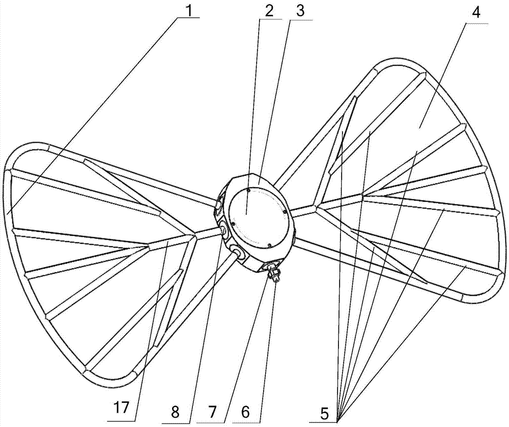
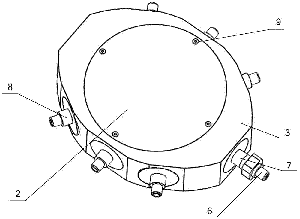
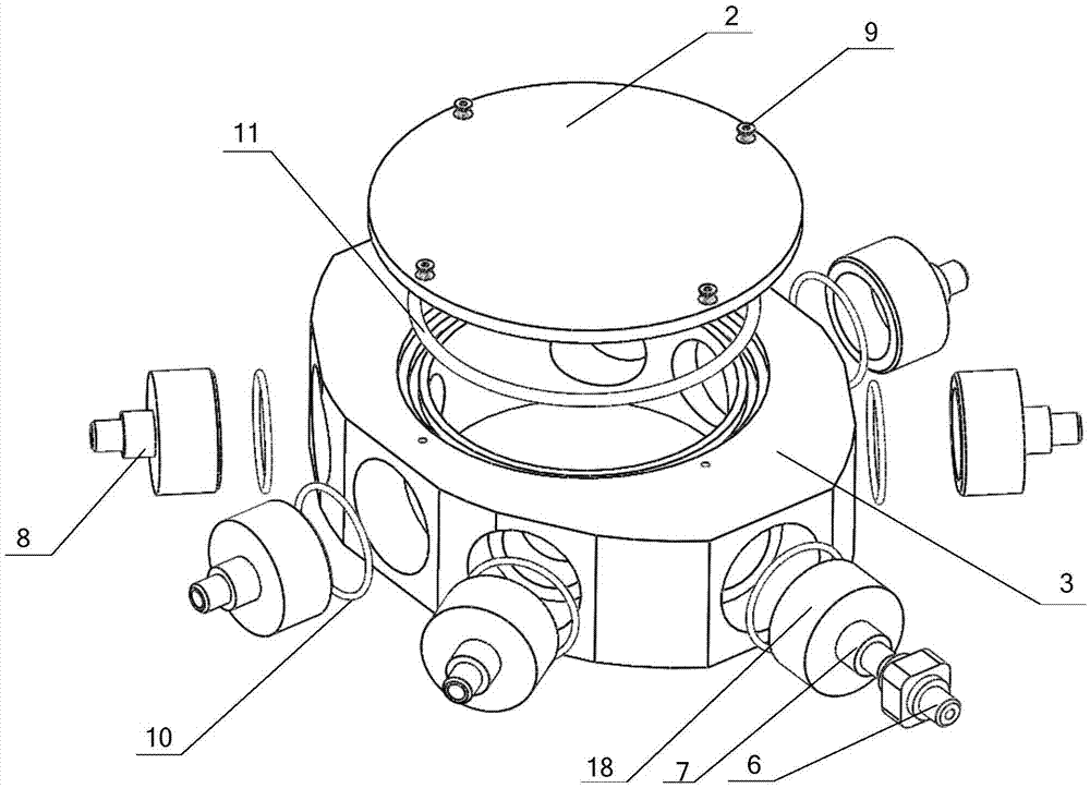
[0020] Such as figure 1 , figure 2 As shown, the present invention includes a trunk part and wing membrane groups symmetrically distributed on both sides of the trunk part with the same structure, wherein the trunk part includes a trunk end cover 2, a central trunk 3 and a trunk air chamber 16, and the trunk air chamber 16 accommodates In the central torso 3, the top is provided with the torso end cover 2 installed on the top of the central torso 3, and the central torso 3 is sealed and connected with the main inflation port 7 communicated with the trunk air chamber 16, and the main inflation port 7 is equipped with an inflatable The switch valve 6 and the central trunk 3 on both sides of the main inflation port 7 are sealed and connected with a plurality of branch inflation ports 8 communicating with the trunk air chamber 16 . The wing membrane group on e...


PUM


Abstract

The invention relates to a bionic, inflatable and deployable structure. A trunk air chamber is contained in a central trunk. The upper portion of the structure is provided with a trunk end cover installed at the top of the central trunk. A main inflation inlet communicating with the trunk air chamber is connected to the central trunk in a sealed mode. An inflation switching valve is installed on the main inflation inlet. A plurality of branch inflation inlets communicating with the trunk air chamber are connected to the positions, on the two sides of the main inflation inlet, of the central trunk in a sealed mode correspondingly. Wing membrane sets on the sides each comprise a wing membrane, a main inflation vein and a linear main inflation vein, and the main inflation vein and the linear main inflation vein are embedded in the wing membrane. Each main inflation vein communicates with the corresponding branch inflation inlet on the same side. The linear main inflation veins are located in the main inflation veins. One ends of the linear main inflation veins communicate with the main inflation veins, and the other ends of the linear main inflation veins communicate with the branch inflation inlets in the same side. The main inflation veins and the linear main inflation veins are all embedded into the wing membranes. The bionic, inflatable and deployable structure does not need to be driven by a motor, and is ingenious in structure and low in weight, and a large deployable area can be obtained through a small folding size.

Description

technical field [0001] The invention relates to an expandable structure, in particular to a bionic inflatable expandable structure based on the development and development of a butterfly's emergence. Background technique [0002] With the continuous development and wide application of spacecraft technology, the structure and function of the spacecraft are constantly changing and becoming more and more complex. Various structures and mechanisms are required to complete the corresponding tasks. As an important structure, the deployable structure has become a spacecraft structure an essential component of. A deployable structure is a structure that realizes a certain part of a spacecraft from an initial collapsed configuration to a final deployed configuration and maintains this configuration. It is widely used in the aerospace field, such as satellite deployment antennas, spacecraft solar arrays, planetary Rover solar panels, alien space base modules and vehicles, and more. ...

Claims


Application Information

Patent Timeline
IPC IPC(8): B64G1/22
CPCB64G1/222B64G1/2227
Inventor 刘金国陈科利陈航张鑫白思航
Owner SHENYANG INST OF AUTOMATION - CHINESE ACAD OF SCI
Learn More