Composite type axial cold extruding steel bar connecting sleeve and mounting tool
A technology for steel bar connecting sleeves and installation tools, which is applied in the direction of hand-held tools, manufacturing tools, structural elements, etc., can solve the problems of wasted working hours, heavy extruders, and low efficiency, so as to avoid load burden, shorten construction time, and reduce construction costs. low effect
- Summary
- Abstract
- Description
- Claims
- Application Information
AI Technical Summary
Problems solved by technology
Method used
Image

Examples
Embodiment 1
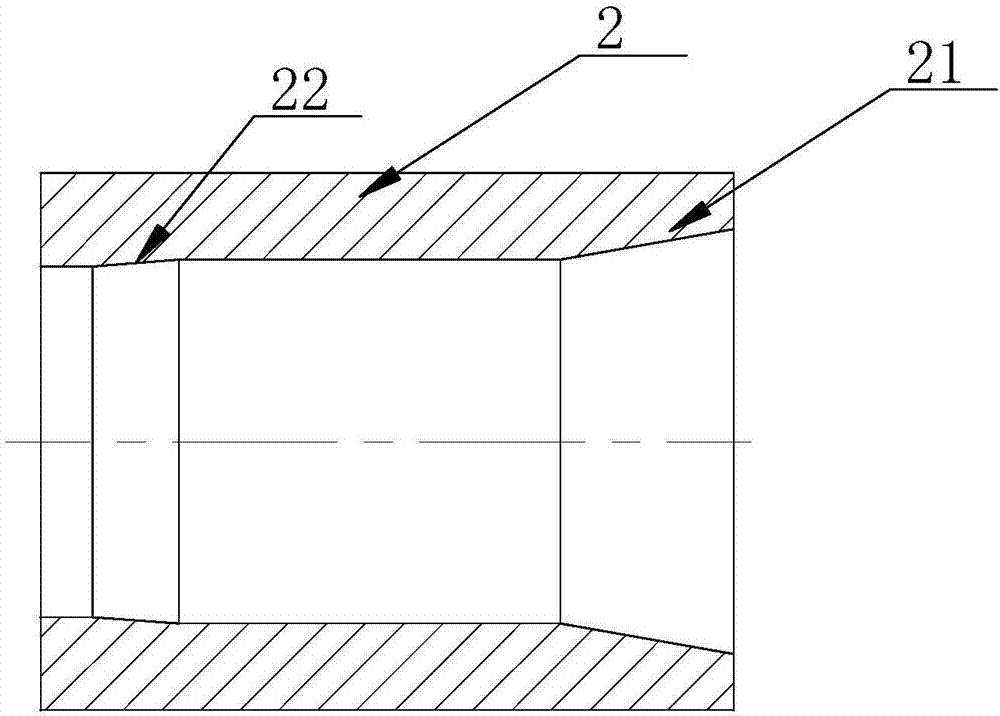
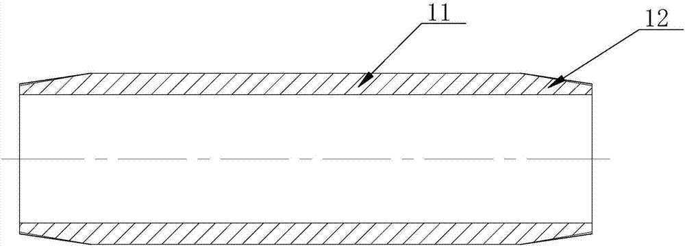
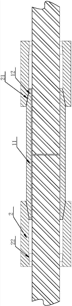
[0042] figure 1 It is a cross-sectional view of the overcoat of the composite axial cold extruded steel bar connecting sleeve of embodiment 1; figure 2 It is a cross-sectional view of the inner sleeve in Embodiment 1; image 3 It is a sectional view of embodiment 1 set on the steel bar. In the figure, the meanings of each mark are as follows:
[0043] 11. The sleeve part of the inner sleeve; 12. The outer tapered part; 2. The jacket; 21. The inner tapered part; 22. The closing chamfer.
[0044] Composite axial cold extruded steel connection sleeve, including inner sleeve and outer sleeve 2, the inner sleeve has an inner sleeve sleeve part 11, and the inner sleeve sleeve part 11 is a complete At least one end of the outer surface of the inner sleeve part 11 is provided with an outer tapered part 12, and the diameter of the outer end of the outer tapered part 12 along the length direction of the inner sleeve part 11 is smaller than that of the outer tapered part 12 The diam...
Embodiment 2
[0064] Figure 4 is a sectional view of the cross section of the inner sleeve in embodiment 2; Figure 5 It is the sectional view of the cross section of the inner sleeve stuck on the reinforcing bar in embodiment 2; Figure 6 It is a cross-sectional view of the inner sleeve clamped on the steel bar in the second embodiment along the axial direction of the steel bar. In the figure, the same symbols as those in the drawings of Embodiment 1 still use the definitions of the symbols in Embodiment 1. The meanings of the newly appearing marks are as follows: 13. Axial ribs.
[0065] The difference between this embodiment and the above-mentioned embodiments is that: the outer surface of the sleeve part 11 of the inner sleeve is provided with an axial rib 13, the axial rib 13 extends in the axial direction, and the direction of the axial rib 13 faces the inner sleeve. The surface of the end face of the cylindrical portion 11 is an extension of the outer tapered portion 12 . Specif...
Embodiment 3
[0068] Figure 7 It is a cross-sectional view of the inner sleeve in embodiment 3; Figure 8 A schematic diagram of extrusion of the inner sheath by the outer sheath on the inner sheath in Example 3. In the figure, the same symbols as those in the drawings of Embodiment 1 still use the definitions of the symbols in Embodiment 1. The meanings of the newly appearing marks are as follows: 14. Outer flange.
[0069] The difference between this embodiment and Embodiment 1 is that: one end of the inner sleeve portion 11 is provided with an outer tapered portion 12 , and the other end of the inner sleeve portion is also provided with an outer flange portion 14 .
[0070] When one end is the outer tapered portion 12 and the other end is the flange portion, only one end needs to be provided with an outer sleeve 2 to complete the extrusion operation.
PUM
| Property | Measurement | Unit |
|---|---|---|
| Cone angle | aaaaa | aaaaa |
| Length | aaaaa | aaaaa |
Abstract
Description
Claims
Application Information
 - Generate Ideas
- Intellectual Property
- Life Sciences
- Materials
- Tech Scout
- Unparalleled Data Quality
- Higher Quality Content
- 60% Fewer Hallucinations
Browse by: Latest US Patents, China's latest patents, Technical Efficacy Thesaurus, Application Domain, Technology Topic, Popular Technical Reports.
© 2025 PatSnap. All rights reserved.Legal|Privacy policy|Modern Slavery Act Transparency Statement|Sitemap|About US| Contact US: help@patsnap.com