
Smoke exhaust structure for anti-freezing gas engine

A technology of gas engine and smoke exhaust pipe, which is applied in the direction of combustion method, exhaust gas device, combustion product treatment, etc., can solve the problem of low energy utilization rate of antifreeze gas engine, achieve low transformation cost, improve thermal efficiency, and energy utilization high rate effect

Inactive Publication Date: 2017-06-30
弘毅天承知识产权股份有限公司
View PDF1 Cites 0 Cited by
  • Summary
  • Abstract
  • Description
  • Claims
  • Application Information

AI Technical Summary

Problems solved by technology

[0005] The invention provides an antifreeze gas engine smoke exhaust structure, which is installed on the gas engine for exhausting smoke, so as to solve the problem of low energy utilization rate of the existing antifreeze gas engine

Method used


Image

  • Smoke exhaust structure for anti-freezing gas engine
  • Smoke exhaust structure for anti-freezing gas engine
  • Smoke exhaust structure for anti-freezing gas engine

Examples


Embodiment 1

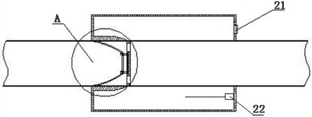
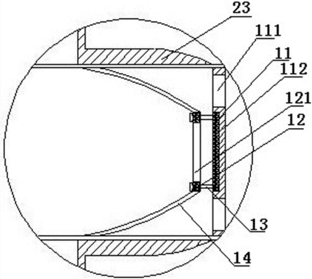
[0018] Such as Figure 1-Figure 3 As shown, a smoke exhaust structure of an antifreeze gas engine includes a smoke exhaust pipe 1 and a fan connected to each other. The inside of the smoke exhaust pipe 1 is provided with a circular fixing plate 11 with the same diameter as the smoke exhaust pipe 1. The central axis of the smoke exhaust pipe 1 of the fixed plate 11 coincides, the central position of the fixed plate 11 is inlaid with a fixed magnetic plate 112, and the fixed plate 11 is provided with some fixed smoke outlet holes 111 near the edge position; There is a non-elastic connection bag 14 sealingly connected to the inner wall of the smoke exhaust pipe 1. The non-elastic connection bag 14 is provided with a movable magnetic plate 12 parallel and coaxial with the fixed plate 11. The center of the movable magnetic plate 12 is provided with Active smoke hole 121.

[0019] In this embodiment, a guide rod 13 is provided between the movable magnetic plate 12 and the fixed pla...

Embodiment 2

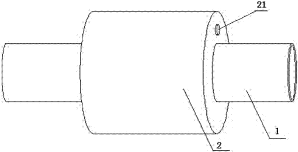
[0023] On the basis of the smoke exhaust structure of an antifreeze gas engine described in Example 1, it is further optimized. The outer sealing sleeve of the smoke exhaust pipe 1 is provided with a heat preservation sleeve 2, and the heat preservation sleeve 2 and the smoke exhaust pipe 1 A thermal insulation cavity is formed, and a water injection port 21 connected to the thermal insulation cavity is provided on the thermal insulation sleeve 2. A temperature control electric heating device 22 is provided inside the thermal insulation cavity, and an insulation layer is provided on the side of the thermal insulation cavity close to the movable magnetic plate 12. twenty three.

[0024] This embodiment mainly relies on the relatively large specific heat capacity of water, which can store heat, and makes full use of the waste heat of flue gas to heat the water in the heat preservation cavity to store energy, maintain the temperature of the part connected to the exhaust pipe 1 and...


PUM


Abstract

The invention discloses a smoke exhaust structure for an anti-freezing gas engine and relates to the field of gas water heaters. The smoke exhaust structure comprises a smoke exhaust pipe and a fan which are mutually connected. A fixed plate with the size the same as the pipe diameter of the smoke exhaust pipe is arranged in the smoke exhaust pipe. The central axis of the fixed plate coincides with the central axis of the smoke exhaust pipe. A fixed magnetic plate is embedded into the center position of the fixed plate. Multiple fixed smoke outlet holes are annularly formed in the position, close to the edge position, of the fixed plate. A non-elastic connecting bag connected to the inner wall of the smoke exhaust pipe in a sealed manner is arranged on the outer side of the fixed plate. A movable magnetic plate which is parallel to the fixed plate and coaxial with the fixed plate is arranged on the non-elastic connecting bag. A movable smoke outlet hole is formed in the center position of the movable magnetic plate. According to the working principle, by arranging a gas reverse flow prevention structure, the situation that cold air enters the gas engine through the smoke exhaust pipe and freezes and damages a water pipe is prevented, the gas engine structure is not changed, only a smoke exhaust structure is replaced, the improvement cost is low, the energy utilization rate of the gas engine is high, and the problem that the energy utilization rate of an existing anti-freezing gas engine is low is solved.

Description

technical field [0001] The invention relates to the field of gas water heaters, in particular to a smoke exhaust structure for an antifreeze gas engine. Background technique [0002] Since the heat exchange medium of the gas engine is water, it cannot be installed outdoors in the north. However, due to factors such as the difficulty in installing the exhaust pipe when installed indoors, most users do not install the exhaust pipe in actual use. Therefore, in winter, because the smoke cannot be exhausted, accidents of "poisoning" of personnel occur from time to time. It is also very common to install the smoke exhaust pipe, and because the cold wind enters the gas engine through the smoke exhaust pipe in winter, the phenomenon of freezing and cracking the water pipe is also very common. Therefore, the installation and use of gas engines in the north has indeed brought a lot of inconvenience to users, which has affected the development of gas engines in the north. [0003] T...

Claims


Application Information

Patent Timeline
Patent Type & Authority Applications(China)
IPC IPC(8): F24H9/00F23J13/08F23J13/02
CPCF24H9/0031F23J13/025F23J13/08
Inventor 樊明伟
Owner 弘毅天承知识产权股份有限公司
Learn More