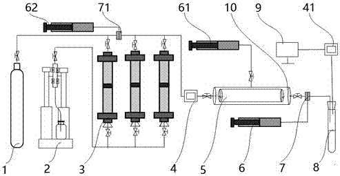
Experimental device researching influence of formation water with high degree of mineralization on CO2 flooding
A high-salinity, experimental device technology, applied in the field of displacement, can solve the problems of unsatisfactory vacuum performance of the device, low accuracy of collected experimental data, lack of corrosion resistance and oleophobicity, etc. Long life, reduced permeability effect
- Summary
- Abstract
- Description
- Claims
- Application Information
AI Technical Summary
Problems solved by technology
Method used
Image
Examples
Embodiment 1
[0021] like figure 1 As shown, a study on the effect of high-salinity formation water on CO 2 The experimental device of flooding effect includes gas cylinder 1, rock core holder 10, gas-liquid separation device 8, gas cylinder 1 is connected with piston container 3, the top of piston container 3 is connected with back pressure valve 71 and pressure gauge 4, piston container 3 The bottom is connected to the ISCO pump 2, the pressure gauge 4 is connected to the core holder 10, the outlet end of the core holder 10 is connected to the gas-liquid separation device 8, and the gas-liquid separation device 8 is connected to the host computer 9 through the gas flow meter 41.
[0022] The back pressure valve 71 is connected with the back pressure pump 62, which will not cause the back pressure to drop and the back pressure fluctuation is small, effectively keeping the back pressure at the injection end of the rock core 5 constant.
[0023] The side of the core holder 10 is connected w...
Embodiment 2
[0034] like figure 1 As shown, a study on the effect of high-salinity formation water on CO 2 The experimental device of flooding effect includes gas cylinder 1, rock core holder 10, gas-liquid separation device 8, gas cylinder 1 is connected with piston container 3, the top of piston container 3 is connected with back pressure valve 71 and pressure gauge 4, piston container 3 The bottom is connected to the ISCO pump 2, the pressure gauge 4 is connected to the core holder 10, the outlet end of the core holder 10 is connected to the gas-liquid separation device 8, and the gas-liquid separation device 8 is connected to the host computer 9 through the gas flow meter 41.
[0035] The back pressure valve 71 is connected with the back pressure pump 62, which will not cause the back pressure to drop and the back pressure fluctuation is small, effectively keeping the back pressure at the injection end of the rock core 5 constant.
[0036] The side of the core holder 10 is connected w...
Embodiment 3
[0047] like figure 1 As shown, the core holder 10 in the device is made of 316 stainless steel, the diameter of the core 5 is 25mm, the length of the core 5 is 25-35mm, and the maximum pressure is 70MPa. The inner cavity of the core holder 10 is provided with a sealed lead sleeve. A sealing liquid is injected into the outside of the sealed lead sleeve to apply a uniform confining pressure (ring pressure) to the rock core 5 to ensure that no leakage occurs when the test fluid passes through the rock core 5 . The confining pressure is dynamically tracked by the displacement pump, and generally the confining pressure is about 2MPa higher than the displacement pressure. In the device, lead sleeves are used to replace commonly used rubber sleeves, which can effectively prevent supercritical CO 2 Corrosion to the gland. The displacement pump adopts ISCO pump 2. The double cylinder of ISCO pump 2 can displace continuously, and the injection volume is accurate and the displacement p...
PUM
 Abstract
Description
Claims
Application Information
 - R&D
- Intellectual Property
- Life Sciences
- Materials
- Tech Scout
- Unparalleled Data Quality
- Higher Quality Content
- 60% Fewer Hallucinations
Browse by: Latest US Patents, China's latest patents, Technical Efficacy Thesaurus, Application Domain, Technology Topic, Popular Technical Reports.
© 2025 PatSnap. All rights reserved.Legal|Privacy policy|Modern Slavery Act Transparency Statement|Sitemap|About US| Contact US: help@patsnap.com


