[0066] In order to make the object, technical solution and advantages of the present invention clearer, the present invention will be further described in detail below in conjunction with the accompanying drawings and embodiments. It should be understood that the specific embodiments described here are only used to explain the present invention, not to limit the present invention.
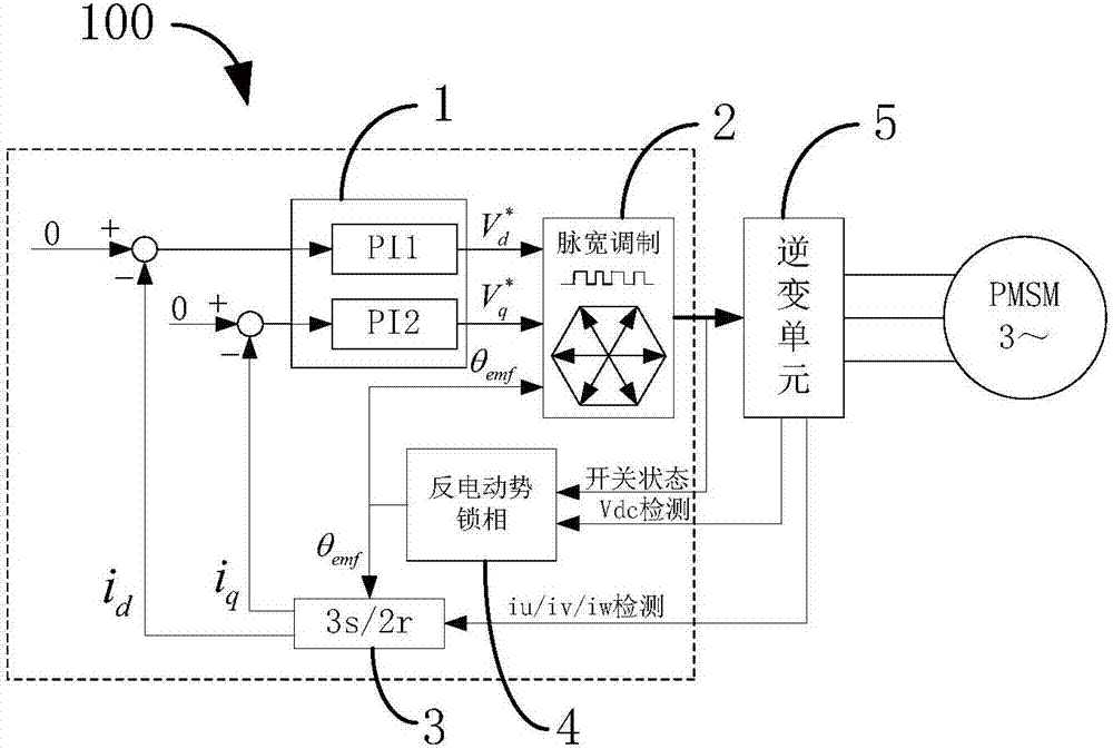
[0067] The invention provides an open-loop control startup method and device for a permanent magnet synchronous motor. Open-loop control starts the huge inrush current generated by the motor. This low-cost open-loop control starting method and system does not require a voltage detection device, and the hardware detection circuit of the existing method is omitted. The present application provides a low-cost open-loop control startup method and device that does not require a counter electromotive force detection device.
[0068] see figure 1 , figure 1 A structural block diagram of an open-loop control starting device 100 for a permanent magnet synchronous motor provided by an embodiment of the present invention, the open-loop control starting device 100 for a permanent magnet synchronous motor includes a proportional-integral regulator 1, a pulse width modulation unit 2, 3s/2r unit 3 , back EMF phase-locked unit 4 and inverter unit 5 . in, figure 1 The part inside the dotted box is realized by software, running in a high-performance digital signal processor (DSP).
[0069] The open-loop control starting method of permanent magnet synchronous motor adopts such as figure 1 The shown open-loop control starting device 100 is implemented. The open-loop control starting method includes steps S1-S5, and the execution order of steps S1-S5 is in no particular order:
[0070] S1. Output the voltage command value of the dq coordinate system according to the two-phase output of the 3s/2r unit 3 by the proportional-integral regulator 1; the step S1 includes sub-steps S11-S13:
[0071] S11, calculate the output value u(t) of the proportional-integral regulator 1, the output and input expressions of the proportional-integral regulator 1 are in the continuous time domain:
[0072]
[0073] Among them, e(t) is the difference between given minus feedback, K p For the gain of the proportional-integral regulator 1, τi is the integral time constant of the proportional-integral regulator 1;
[0074] S12, the proportional-integral regulator 1 includes a PI1 regulator and a PI2 regulator, and the function of these two regulators is to control the output i of the 3s/2r unit 3 d and i q is zero, that is, the output current i of the inverter u i v and i w to zero. The adjustment speed of these two regulators determines the size of the driver inrush current when the algorithm is executed. In order to reduce the inrush current as much as possible, the K of the two regulators p and τ i The self-adaptive method is used for automatic adjustment, and the self-adaptive adjustment rule is:
[0075] K p =f(I s )
[0076] Among them, I s The amplitude of the output current of unit 3 is 3s/2r:
[0077]
[0078] i d and i q is the two-phase output current of the two-phase output of the 3s/2r unit 3;
[0079] S13. The proportional-integral regulator 1 outputs the voltage command value of the dq coordinate system according to the output value u(t) and The output of PI1 and PI2 is the voltage command value in the dq coordinate system and Access to pulse width modulation unit 2.
[0080] S2. Input the voltage command value and the back EMF direction angle output by the back EMF phase-locking unit 4 to the pulse width modulation unit 2, and the pulse width modulation unit 2 outputs to drive the inverter unit 5 according to the volt-second equivalent principle The PWM pulse signal of the switching device; the pulse width modulation unit 2 is used to output the voltage command according to PI1 and PI2 and And the back electromotive force direction θ of back electromotive force phase locking unit 4 output emf , according to the principle of volt-second equivalent to generate a PWM pulse signal for driving the switching device of the inverter.
[0081] S3, using the 3s/2r unit 3 to convert the three-phase output of the inverter unit 5 into the two-phase output in the two-phase rotating coordinate system; the step S3 includes sub-steps S31-S32 :
[0082] S31. This unit is used to transform the three-phase static physical quantity into the two-phase rotating coordinate system. It can be decomposed into two steps to realize, 3s/2s and 2s/2r, the conversion calculation formula of 3s/2s is the following formula, that is, The three-phase output is converted to i α and i β :
[0083]
[0084] Among them, i u i v and i w is the three-phase current of the three-phase output;
[0085] S32. Calculate the two-phase output in the two-phase rotating coordinate system, that is, the conversion formula of 2s/2r is:
[0086]
[0087] Wherein, θ is the direction angle of the back EMF of the back EMF phase-locking unit 4, and the magnitude of the vector remains unchanged before and after transformation.
[0088] S4. Calculate the three-phase output and the direction angle of the back EMF according to the switching device state and the DC bus voltage of the inverter unit 5 by the back EMF phase-locked unit 4; the voltage equation of the permanent magnet synchronous motor in a steady state :
[0089]
[0090] In the formula, the subscripts "M" and "T" represent the physical quantities on the M-axis and T-axis after coordinate transformation. The M-axis is defined as the direction that coincides with the flux linkage of the motor rotor, and the T-axis is defined as forward rotation ahead of the M-axis by 90 ° The direction of the electrical angle. R s is the stator resistance, ω e is the synchronous angular frequency (also known as "synchronous rotational frequency" or "motor rotational speed"), is the amplitude of the rotor flux linkage, according to the principle that the amplitude of the coordinate transformation remains unchanged, if the control i d and i q is zero, which controls i M and i T is zero, the above formula can be simplified as:
[0091]
[0092] That is to say, when the output current of the driver is zero, the output voltage of the driver is equal to the back electromotive force of the motor Because the difficulty of controlling the current to zero is that the transformation angle of the 3s/2r transformation unit should coincide with the direction of the back electromotive force of the motor, so the acquisition of the direction angle of the back electromotive force is the core of the reliable operation of the algorithm. The present invention uses three-phase phase-locked loop technology to lock The direction of the counter electromotive force, its principle block diagram is shown in the attached figure 2.
[0093] Said step S4 comprises sub-steps S41-S44:
[0094] S41. Using the output voltage reconstruction unit to calculate the three-phase output voltage V according to the state of the switching device of the inverter unit 5 and the DC bus voltage u , V v and V w; figure 2 Among them, the three-phase PLL and the 3s/2r unit 3 are composed of an output voltage reconstruction unit 41 , a 3s/2r coordinate transformation unit 3 (namely the 3s/2r unit 3 ), a PI regulator 42 and an integrator 43 . The output voltage reconstruction unit calculates the three-phase output voltage V according to the switching state of the inverter unit 5 and the DC bus voltage u , V v and V w.
[0095] S42. Using the 3s/2r unit 3 to output the three-phase output voltage V u , V v and V w Converted to V in a two-phase rotating coordinate system d and V q; The 3s/2r coordinate transformation unit converts the three-phase voltage V u , V v and V w Converted to V in a two-phase rotating coordinate system d and V q , the PI regulator is used to eliminate the angular deviation between the estimated back EMF and the actual back EMF direction.
[0096] S43, eliminate the angle deviation between the estimated back EMF and the actual back EMF direction by the PI regulator; the step S43 includes sub-steps S431-S433:
[0097] S431. When the d-axis direction lags behind the actual back EMF direction, use the PI regulator to increase the rotation speed of the d-axis; as image 3 As shown, when the d-axis direction lags behind the actual back EMF direction, the PI regulator will cause the d-axis to rotate faster.
[0098] S432. When the direction of the d-axis is ahead of the actual back EMF direction, the rotation speed of the d-axis is reduced by the PI regulator; as image 3 As shown, conversely, when the d-axis direction is ahead of the actual back EMF direction, the PI regulator will cause the d-axis rotation speed to slow down.
[0099] S433. When the d-axis direction coincides with the actual back EMF direction, the back EMF phase is locked successfully, and:
[0100] V q =0
[0101] V d =|emf|
[0102]
[0103] Among them, |emf| is the magnitude of the back EMF of the motor, is the estimated back EMF direction angle, θ emf is the actual back EMF orientation angle. When the d-axis coincides with the actual back EMF, the back EMF phase is locked successfully, at this time V q equal to zero, V d Equal to the magnitude of the motor's back EMF |emf|, the estimated back EMF direction angle Equal to the actual back EMF direction angle θ emf.
[0104] S44. Using the back EMF phase-locked unit 4 to output the synchronous rotation frequency ω according to the feed-forward frequency e. The feedforward frequency is obtained according to the rotational speed at the time of shutdown. ω f It is the feed-forward frequency, which can be given according to the rotational speed at the moment of shutdown or calculated according to the output voltage at the initial stage of algorithm execution, and the back EMF phase-locked unit 4 can also output the synchronous rotation frequency (motor rotation speed) ω e.
[0105] S5. Using the inverter unit 5 to convert the PWM pulse signal into a strong voltage to control the motor. That is to say, the inverter unit 5 converts the switching signal output by the pulse width modulation unit 2 into a strong electric voltage and controls the motor to start. If the rotation speed of the motor at the starting moment is lower than the preset value, the motor is stopped by short-circuiting the brake, and the motor is started again according to a conventional starting method. see Figure 4 , Figure 4 A flow chart of starting a motor provided by an embodiment of the present invention. If the motor rotates at a low speed or stands still when starting, the back EMF will be very small, so there is no need to estimate the magnitude and direction of the back EMF. The system will bring the motor to a standstill by short-circuiting the brake briefly, and then start according to the normal starting method.
[0106] Preferably, the open-loop control starting method also includes steps S6-S7:
[0107] S6. Execute the zero-current control algorithm and the back-EMF phase-locking algorithm to obtain the magnitude of the current current and estimate the stability of the back-emf, and save the back-emf amplitude |emf|, the actual moment when the back-emf phase-locking unit 4 successfully tracks The direction angle of the back EMF and the estimated synchronous rotation frequency ω e. That is, after the drive is started, the zero-current control algorithm and the back-EMF phase-locking algorithm are executed, and the magnitude of the current and the stability of the estimated back-emf are continuously judged during the period. If the tracking is successful, the back-emf amplitude |emf| at this time is saved. Back EMF Direction Angle and the estimated motor speed ω e.
[0108] S7, for u d , u q and θ are assigned initial values, that is, to assign initial values to each variable in the open-loop control operation:
[0109] u d =0
[0110]
[0111]
[0112] Among them, T s For the sampling time of the current loop, each variable of the open-loop control is assigned an initial value and then switched to the open-loop control operating state. u d and u q is the two-phase voltage of the dq coordinate system; θ is the initial value of the direction angle of the back EMF.
[0113] Various operations of embodiments are provided herein. In one embodiment, the one or operations described may constitute one or computer-readable instructions stored on a computer-readable medium, which when executed by an electronic device will cause the computing device to perform the operations described. The order in which some or all operations are described should not be construed to imply that these operations are necessarily order-dependent. Alternative orderings will be appreciated by those skilled in the art with the benefit of this description. Also, it should be understood that not all operations need to be present in every embodiment provided herein.
[0114] Also, the word "preferred" as used herein means serving as an example, instance or illustration. Any aspect or design described herein as "preferred" is not necessarily to be construed as advantageous over other aspects or designs. Rather, use of the word "preferably" is intended to present concepts in a concrete manner. As used in this application, the term "or" is intended to mean an inclusive "or" rather than an exclusive "or". That is, unless otherwise specified or clear from context, "X employs A or B" is meant to naturally include either of the permutations. That is, if X employs A; X employs B; or X employs both A and B, then "X employs A or B" is satisfied in any of the foregoing instances.
[0115] Moreover, although the disclosure has been shown and described with respect to one or an implementation, equivalent alterations and modifications will occur to others skilled in the art upon the reading and understanding of this specification and the annexed drawings. The present disclosure includes all such modifications and variations and is limited only by the scope of the appended claims. With particular regard to various functions performed by the above-mentioned components (eg, elements, etc.), terms used to describe such components are intended to correspond to any component that performs the specified function of the component (eg, it is functionally equivalent) Even if there are no structural equivalents to the disclosed structures that perform the functions in the exemplary implementations of the present disclosure shown herein (unless otherwise indicated). Furthermore, although a particular feature of the present disclosure has been disclosed with respect to only one of several implementations, such feature may be combined with one or other features of other implementations as may be desirable and advantageous for a given or particular application. combination. Moreover, to the extent the terms "comprises", "has", "comprising" or variations thereof are used in the detailed description or the claims, such terms are intended to be encompassed in a manner similar to the term "comprising".
[0116] Each functional unit in the embodiment of the present invention may be integrated into one processing module, or each unit may physically exist separately, or multiple or more of the above units may be integrated into one module. The above-mentioned integrated modules can be implemented in the form of hardware or in the form of software function modules. If the integrated modules are realized in the form of software function modules and sold or used as independent products, they can also be stored in a computer-readable storage medium. The storage medium mentioned above may be a read-only memory, a magnetic disk or an optical disk, and the like. Each of the above devices or systems may execute the storage method in the corresponding method embodiment.
[0117] In summary, although the present invention has been disclosed above with preferred embodiments, the above preferred embodiments are not intended to limit the present invention, and those of ordinary skill in the art can make various modifications without departing from the spirit and scope of the present invention. Therefore, the protection scope of the present invention shall be determined by the scope defined in the claims.