Nasal catheter limiting tool fixed in nasal cavity

A nasal cavity and catheter technology, applied in catheters and other directions, can solve problems such as unsatisfactory positioning effect and use comfort, poor patient experience in operation methods, complex device structure combination, etc., achieve simple and ingenious operation methods, and avoid operation risks and discomfort Feeling and avoiding the effects of external stimuli

Inactive Publication Date: 2017-07-04
ZHEJIANG FERT MEDICAL DEVICE +1
View PDF5 Cites 4 Cited by
  • Summary
  • Abstract
  • Description
  • Claims
  • Application Information

AI Technical Summary

Problems solved by technology

For example, the patent document with application number CN2014203983382 discloses an improved nasogastric tube structure, which includes a nasogastric tube and a limiting structure for fixing the nasogastric tube, the limiting structure includes the longitudinal direction of the nasogastric tube The limiting body passing through and the fixing belt passing through the limiting body transversely and the adjusting piece for adjusting the length of the fixing belt, the free end of the fixing belt passes through the adjusting piece and is fixed by the adjusting piece; The limiter includes a nasogastric tube passing ring that can be opened and closed. The nasogastric tube passing ring is composed of a ring body with an opening and ring body connectors arranged at both ends of the ring body. The device structure combination is complex, The operation steps are cumbersome, and both the operation method of the medical staff and the experience of the patient are poor, and the position-limiting effect and comfort of use are still not ideal, which may easily cause discomfort to the patient and even accidental extubation.
In addition, too many component connections will cause the face to be polluted by bacteria and viruses due to the accumulation of nasal secretions, and even cause new infections

Method used


Image

  • Nasal catheter limiting tool fixed in nasal cavity
  • Nasal catheter limiting tool fixed in nasal cavity
  • Nasal catheter limiting tool fixed in nasal cavity

Examples


Embodiment Construction

[0033] Below in conjunction with accompanying drawing, the present invention will be further described by specific embodiment:

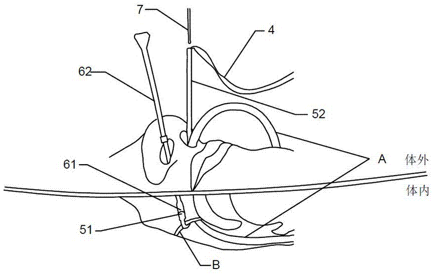
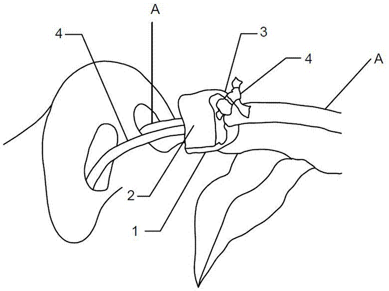
[0034] refer to figure 1 , figure 2 , image 3 , Figure 4 , a method for limiting the intranasal catheter A, which is suitable for limiting the intranasal catheter A inserted into the human body through the nasal cavity, and connecting the intranasal catheter A to the limiting device bypassing the rear of the nasal septum B of the human body. Obviously, the rear mentioned in this patent refers to the space behind the end of the nasal septum B corresponding to the end outside the body.

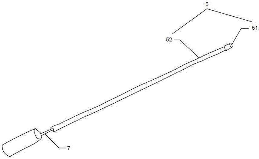
[0035] The position-limiting device includes a flexible frenulum 4, which can be a flexible thread, belt, or bundle, and can be a cotton thread or a cable tie; after the frenulum 4 is guided by the first guide member 5 and inserted into the first nostril, The second guide part 6 inserted into the second nostril guides and pulls out the second nostril to bypass t...


PUM


Abstract

The invention discloses a nasal catheter limiting tool fixed in a nasal cavity. The nasal catheter limiting tool comprises a flexible strap, a nasal catheter clamping part, a first guide part and a second guide part, wherein the strap is connected to the nasal catheter clamping part; the first guide part and the second guide part are provided with ends which are magnetically attractive; the strap is connected to the first guide part; the nasal catheter clamping part is used for connecting the strap and is fixed to a nasal catheter; the first guide part is used for guiding the strap to enter into a first nostril of a human body; and the second guide part is used for attracting and connecting the first guide part and is used for guiding the first guide part, together with the strap which is connected to the first guide part, to wind around the back side of human nasal septum and run out of a second nostril. The limiting tool provided by the invention is simple to operate, good in comfort in a patient and is safe and reliable, and the limiting tool can prevent extubation and catheter removal by accidents.

Description

technical field [0001] The invention relates to the technical field of nursing applications, in particular to a positioning method and tool for a nasal built-in catheter fixed through the nasal cavity. Background technique [0002] At present, after the intranasal catheter (such as gastric tube) used by clinical patients is inserted into the body through the nasal cavity for positioning, it is usually fixed on the nose and face with a special applicator. The patch fixes the intranasal catheter by attaching to the sides and front of the patient's nose. The main problems with this fixation method include: [0003] First of all, fix the built-in nasal catheter by applying. At present, there is no special nasal applicator to fix the indwelling catheter outside the body. It needs to rely on manual temporary editing. In this way, it may be caused by scissors and Hand contact increases the chance of contamination and infection. In addition, it is easy to cause insufficient adhesi...

Claims


Application Information

Patent Timeline
Patent Type & Authority Applications(China)
IPC IPC(8): A61M25/02
CPCA61M25/02A61M2025/0226A61M2025/0253
Inventor 陈钧徐虹霞徐凌丽李秀萍马建强苏卫东李慎贵
Owner ZHEJIANG FERT MEDICAL DEVICE
Why Eureka
Try Eureka