Workpiece support system
一种支承系统、工件的技术,应用在制造工具、金属加工、车辆部件等方向,能够解决难传送、复杂结构等问题,达到简化结构的效果
- Summary
- Abstract
- Description
- Claims
- Application Information
AI Technical Summary
Problems solved by technology
Method used
Image
Examples
Embodiment approach 1
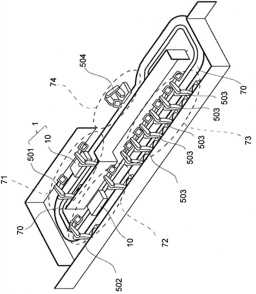
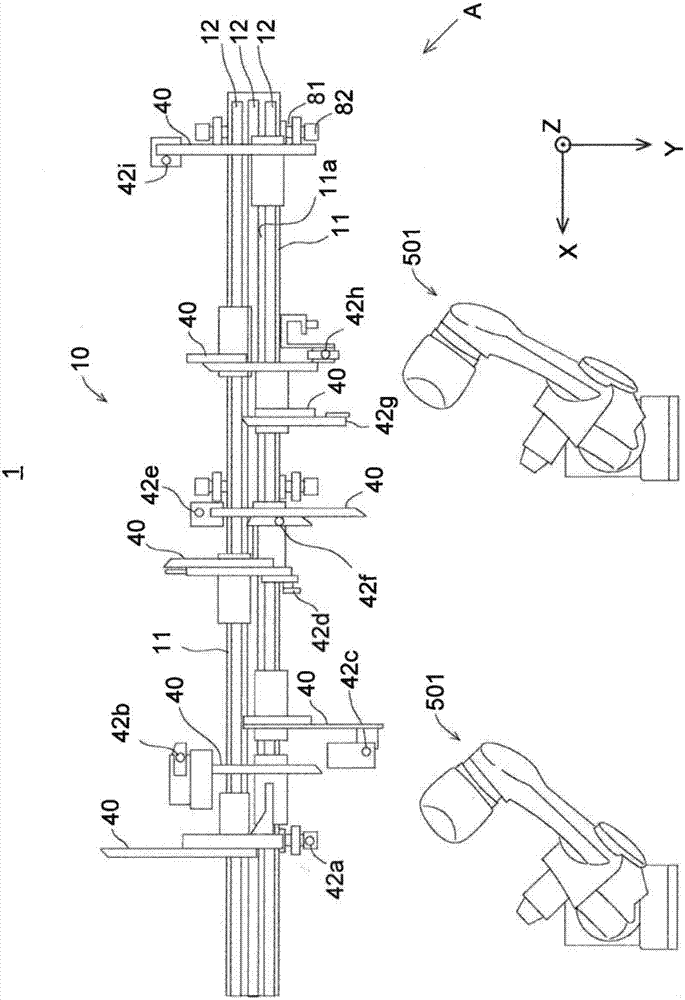
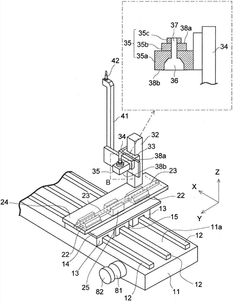
[0022] (Embodiment 1) A workpiece support system according to Embodiment 1 will be described. First, the configuration of the workpiece support system will be described. figure 1 It is a perspective view of a vehicle welding assembly line employing the workpiece support system according to the first embodiment. like figure 1 As shown, in a vehicle welding assembly line 70 , a self-propelled conveyor loops along line 70 and has a workpiece support device 10 mounted on the self-propelled conveyor. Predetermined steps are assigned to each predetermined position in line 70 . The self-propelled conveyor on which the workpiece supporting device 10 is mounted goes through a cycle of a series of steps: from a vehicle type switching step 71 through a workpiece setting step 72, a welding / deposition assembling step 73, and a finished product removal step 74 Go to the vehicle type switching step 71 for the next vehicle type. In these steps, predetermined operations are performed by de...
Embodiment approach 2
[0070] (Embodiment 2) Next, Embodiment 2 will be described. Embodiment 2 is a workpiece support device 10 mounted on a rotary table. Figure 7 is a plan view illustrating the workpiece support system according to Embodiment 2. like Figure 7 As shown, the workpiece support system 2 in Embodiment 2 is provided with a rotary table 83 . The turntable 83 has, for example, a disk shape. The upper surface of the turntable is divided into two parts, wherein the workpiece supporting device 10a is mounted on one part, and the workpiece supporting device 10b is mounted on the other part.
[0071] A plurality of, for example, four robots are installed around the turntable 83 . In the clockwise direction viewed from above, the robot 501 for the vehicle type switching step 71, the robot 503a for the first welding / bonding assembly step 73, the robot 503b for the second welding / bonding assembly step 73 and a robot 504 for the finished product removal step 74 are arranged around the rota...
Embodiment approach 3
[0073] (Embodiment 3) Next, Embodiment 3 will be described. Embodiment 3 relates to the support portion 42 .
[0074] Figure 8 is a view illustrating a supporting portion of a workpiece supporting device in a workpiece supporting system according to Embodiment 3. FIG. like Figure 8 As shown, the support portion 42 of the support body 40 of the workpiece support device 10 is a combination of a support portion 42a, a support portion 42b, and a support portion 42c. Each support portion 42 has a cylindrical shape.
[0075] The support portion 42 c is fixed to the post 41 of the support body 40 . A recess is formed in the upper surface of the support portion 42c. This recess serves as a spherical bearing 44 . A spherical body 45 is attached to the bottom surface of the bearing portion 42b. The spherical body 45 of the support part 42b fits in the spherical bearing 44 of the support part 42c. Thus, the support portion 42b can be rotated relative to the support portion 42c ...
PUM
 Abstract
Description
Claims
Application Information
 - R&D
- Intellectual Property
- Life Sciences
- Materials
- Tech Scout
- Unparalleled Data Quality
- Higher Quality Content
- 60% Fewer Hallucinations
Browse by: Latest US Patents, China's latest patents, Technical Efficacy Thesaurus, Application Domain, Technology Topic, Popular Technical Reports.
© 2025 PatSnap. All rights reserved.Legal|Privacy policy|Modern Slavery Act Transparency Statement|Sitemap|About US| Contact US: help@patsnap.com


