Automatic feeding device

A technology of feeding device and driving device, which is applied in metal processing and other directions, and can solve problems such as low efficiency and high risk

Active Publication Date: 2017-07-04
无锡诚勇自动化技术有限公司
View PDF7 Cites 5 Cited by
  • Summary
  • Abstract
  • Description
  • Claims
  • Application Information

AI Technical Summary

Problems solved by technology

The existing working method is to manually place steel pipes one by one on the processing machine by workers. On the one hand, this method is inefficient. On the other hand, since the stee...

Method used


Image

  • Automatic feeding device
  • Automatic feeding device
  • Automatic feeding device

Examples


Embodiment Construction

[0019] The present invention will be further explained below in conjunction with specific embodiments.

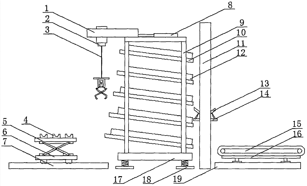
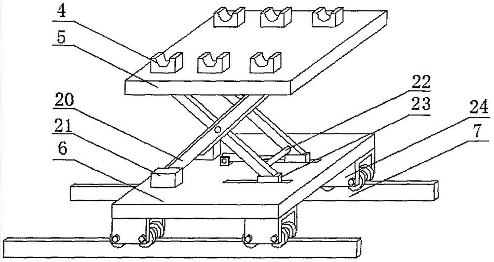
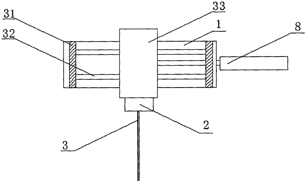
[0020] refer to Figure 1-4 , an automatic feeding device, comprising a base 17, the lower end of the base 17 is provided with a shock absorber for shock absorption, the upper end of the base 17 is provided with a shelf 9 for storing steel pipes, and the shelf 9 is vertically A plurality of placing plates 10 are arranged at equal intervals, and the length of the placing plates 10 decreases successively from top to bottom. Both ends of the placing plates 10 are provided with baffles 12, and one side of the placing plates 10 is provided with a sealing door, and the sealing door is rotatably connected to the Between the two baffles 12, one side of one of the baffles 12 is provided with a driving device, the output shaft of the driving device passes through the baffle 12 and is fixedly connected with one end of the sealing door, and the driving device can drive the sealing door...


PUM


Abstract

The invention discloses an automatic feeding device which comprises a base, wherein a damping device is arranged at the lower end of the base, and a placing rack is arranged at the upper end of the base; a plurality of placing plates are arranged on the placing rack along a vertical direction at equal interval, and the lengths of the placing plates are decreased progressively in order from top to bottom; baffle plates are arranged at the two ends of each placing plate, and a sealing door is arranged on one side of the placing plate and is rotationally connected between the two baffle plates; a driving device is arranged on one side of one baffle plate, and an output shaft of the driving device penetrates through the baffle plate and is fixedly connected with one end of the sealing door. The automatic feeding device realizes automatic steel pipe transfer and transport through the combination of a pipe placing mechanism, a clamping device, a transfer device, etc., increases the storage capacity by the arrangement of the placing rack, can take materials as required, improves the production efficiency, reduces the cost, reduces dangerous accidents, and is suitable for popularization.

Description

technical field [0001] The invention relates to the technical field of automatic feeding, in particular to an automatic feeding device. Background technique [0002] The development of steel pipe production technology began with the rise of the bicycle manufacturing industry, the development of petroleum in the early 19th century, the manufacture of ships, boilers, and aircraft during the two world wars, the manufacture of thermal power boilers after the Second World War, the development of the chemical industry and Drilling, production and transportation of oil and natural gas have strongly promoted the development of steel pipe industry in terms of variety, output and quality. [0003] The steel pipe is used to transfer fluid and powder, exchange heat and produce mechanical parts and containers, what's more it's a kind of economical steel. Using steel pipes to manufacture building structure grids, pillars and mechanical supports can reduce weight, save metal by 20-40%, an...

Claims


Application Information

Patent Timeline
IPC IPC(8): B23Q7/00B23Q7/04
CPCB23Q7/00B23Q7/04
Inventor 赵浩冯浩王璇
Owner 无锡诚勇自动化技术有限公司
Why Eureka
Try Eureka