An oil-water separation device and process for oilfield acidizing fracturing fluid

An oil-water separation device, acid fracturing technology, applied in the direction of grease/oily substance/suspton removal device, special compound water treatment, centrifugal separation water/sewage treatment, etc., can solve the problem of large discharge change and difficult flowback liquid Problems such as standard treatment and difficulty in flowback liquid treatment

Active Publication Date: 2020-07-07
CHINA UNIV OF PETROLEUM (EAST CHINA)
View PDF6 Cites 0 Cited by
  • Summary
  • Abstract
  • Description
  • Claims
  • Application Information

AI Technical Summary

Problems solved by technology

During oilfield operations, a large amount of flowback waste liquid will be produced. The flowback waste liquid contains a large amount of organic additives. At the same time, the additives have more and more components and their stability is getting better and better. Therefore, acidification and fracturing wastewater often It presents the characteristics of high acidity, high stability, high CODcr and high salinity, which makes it more and more difficult to treat this kind of flowback liquid. 1. The construction sites of fracturing operations are extremely scattered, and the wastewater discharge method is intermittent, and the discharge volume varies greatly. This type of wastewater is not suitable for conventional biochemical treatment.
[0003] At present, there are few studies on the treatment of oil-water separation in acidified fracturing flowback fluid. The basic method is to add demulsifiers, flocculants and purifiers before sedimentation treatment, which will make crude oil become aging oil and cannot be refined

Method used


Image

  • An oil-water separation device and process for oilfield acidizing fracturing fluid
  • An oil-water separation device and process for oilfield acidizing fracturing fluid
  • An oil-water separation device and process for oilfield acidizing fracturing fluid

Examples


Embodiment 1

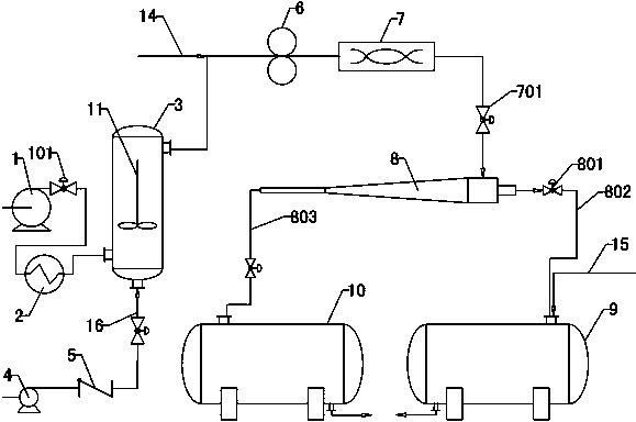
[0028] Refer to attached figure 1 : An oil-water separation device for acidizing and fracturing fluid in an oil field, comprising an acidizing and fracturing flowback fluid delivery pipeline, a heat exchanger 2, a gel breaking device, an emulsion breaking and mixing device, a cyclone separation device, and the outlets of the cyclone separation device are respectively connected The oil storage tank 9 and the sewage tank 10; the acidizing fracturing flowback fluid delivery pipeline is connected to the lower part of the gel breaking device through the heat exchanger 2, the upper part of the gel breaking device is connected to the demulsification mixing device, and the demulsification mixing device is connected to the cyclone The separation device, the overflow port and the underflow port of the cyclone separation device are respectively connected to the oil storage tank 9 and the sewage tank 10 through pipelines.

[0029]The acidizing fracturing flowback fluid delivery pipeline i...

Embodiment 2

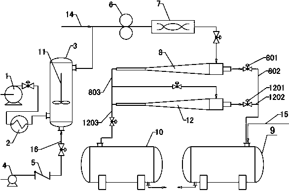
[0040] Refer to attached figure 2 : The cyclone separation device includes a primary cyclone 8 and a secondary cyclone 12, the bottom flow port of the primary cyclone 8 is connected to the inlet of the secondary cyclone 12 and the sewage tank 10 through the primary sewage discharge pipeline 803 respectively , the underflow port of the secondary cyclone 12 is connected to the sewage tank 10 through the secondary sewage discharge pipeline 1203, and the overflow port of the primary cyclone 8 and the overflow port of the secondary cyclone 12 are jointly connected to the oil storage tank 9 , the inlet end of the oil storage tank 9 is also connected to the second demulsifier adding pipe 15 . The overflow port of the primary cyclone 8 and the overflow port of the secondary cyclone 12 are respectively provided with a primary dirty oil discharge pipe 802 and a secondary dirty oil discharge pipe 1202, a primary dirty oil discharge pipe 802 and a secondary dirty oil discharge pipe 1202....

Embodiment 3

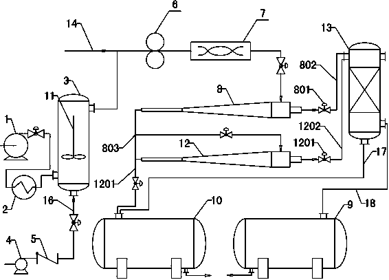
[0043] Refer to attached image 3 : A demulsification tank 13 is provided between the overflow port of the primary cyclone 8 and the overflow port of the secondary cyclone 12 and the oil storage tank 9, and the upper inlet of the demulsification tank 13 is connected to the primary cyclone through a pipeline The overflow port of the device 8 and the overflow port of the secondary cyclone 12, the drain pipe 17 at the bottom of the demulsification tank 13 is connected to the sewage tank 10, and the oil drain pipe 18 at the bottom of the demulsification tank 13 is connected to the oil storage tank 9.

[0044] When the addition of chemical agents is not conducive to the subsequent demulsification and dehydration of crude oil, the present invention adopts two-stage cyclone separation and mechanical demulsification. The acidified fracturing fluid with high oil content is pumped by the pump 1 and delivered to the gel breaking tank 3 through the heat exchanger 2. The heat exchanger 2 c...


PUM


Abstract

The invention discloses an oil-water separation device and process for oilfield acidification fracturing fluid, belonging to the field of sewage and sewage oil treatment equipment. It is characterized in that it includes an acidizing fracturing flowback fluid delivery pipeline, a heat exchanger (2), a gel breaking device, an emulsification mixing device, a cyclone separation device, and an oil storage tank (9 ) and sewage tank (10); the acidizing fracturing flowback fluid delivery pipeline is connected to the lower part of the gel breaking device through the heat exchanger (2), the upper part of the gel breaking device is connected to the demulsification mixing device, and the demulsification mixing device is connected to the cyclone The separation device, the overflow port and the underflow port of the cyclone separation device are respectively connected to the oil storage tank (9) and the sewage tank (10) through pipelines. The invention has the advantages of good degreasing effect, stable process, compact structure, low operating cost, etc., and is especially suitable for sites far away from gathering and transportation treatment stations, and realizes on-site treatment and on-site recovery of flowback liquid.

Description

technical field [0001] The invention discloses an oil-water separation device and process for oilfield acidification fracturing fluid, belonging to the field of sewage and sewage oil treatment equipment. Background technique [0002] Acid fracturing is the use of acid hydraulic action to form cracks in the oil layer, which is called oil layer hydraulic fracturing. The fluid used for fracturing is called fracturing fluid. At present, 95% of fracturing fluids are water-based fracturing fluids, and oil-based fracturing fluids only account for 5%. Various additives are added to the fracturing fluid to increase the viscosity of the fracturing fluid at high temperature, reduce its viscosity at low temperature, and control the fluid loss into the formation. During oilfield operations, a large amount of flowback waste liquid will be produced. The flowback waste liquid contains a large amount of organic additives. At the same time, the additives have more and more components and the...

Claims


Application Information

Patent Timeline
Patent Type & Authority Patents(China)
IPC IPC(8): C02F9/04C02F103/10
CPCC02F1/38C02F1/40C02F9/00C02F2103/10C02F2301/08C02F2305/026
Inventor 王振波刘兆增杜爱勋朱丽云陈阿强蒋文春孙治谦巩志强
Owner CHINA UNIV OF PETROLEUM (EAST CHINA)
Why Eureka
Try Eureka