Drilling bit and rotary drilling rig

A drill bit and piston technology, applied in drill bits, drilling tools, drilling equipment, etc., can solve the problems of blocking rotary drilling rig construction efficiency, long time consumption, pollution, etc.

Active Publication Date: 2017-07-04
北京东方新星勘察设计有限公司
View PDF11 Cites 1 Cited by
  • Summary
  • Abstract
  • Description
  • Claims
  • Application Information

AI Technical Summary

Problems solved by technology

Due to the relatively large friction between the soil and the drill bit and the cohesive force of the soil itself, the excavated soil and the drill bit are tightly stuck together, and it is difficult to pour the soil and it takes a long time.
When the existing rotary drilling rig encounters cohesive soil, it will be difficult to pour the soil if the footage is too large, so the method of drilling at the expense of the depth of a single footage has to be adopted
This drilling method greatly reduces the construction efficiency, seriously blocks the advantages of high construction efficiency of the rotary drilling rig, and often produces harsh noise pollution

Method used


Image

  • Drilling bit and rotary drilling rig
  • Drilling bit and rotary drilling rig

Examples


Embodiment 1

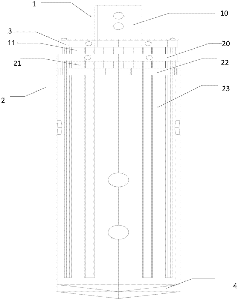
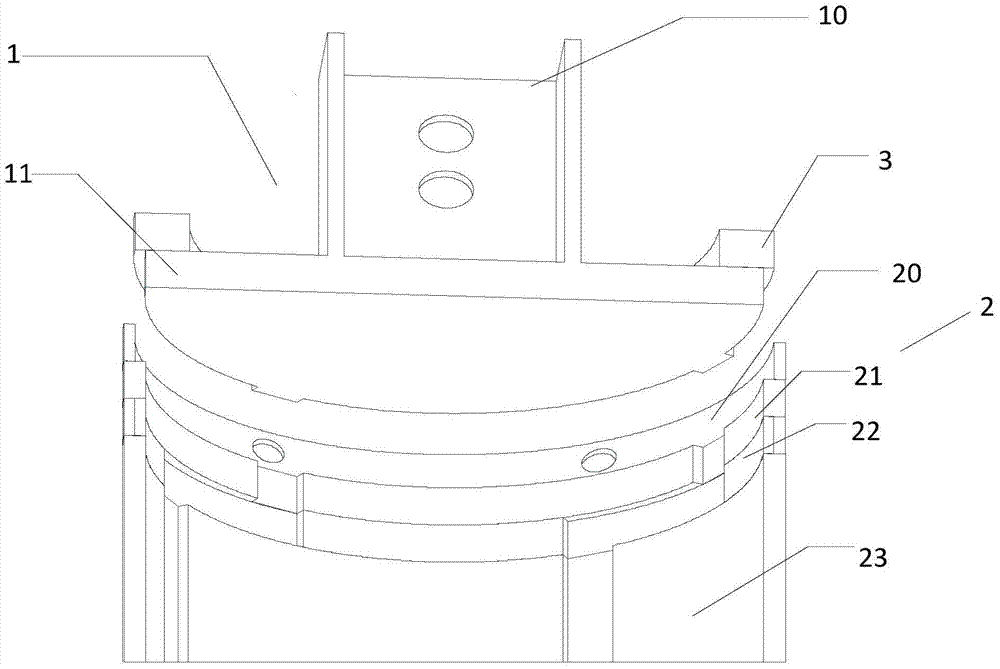
[0031] Such as figure 1 and figure 2 As shown, a drill bit proposed in Embodiment 1 of the present invention includes a piston door 1, a cylinder body 2, an annular top door 3 and a bottom door 4, wherein the piston door 1 has a connecting rod 10 and a disc 11, and the disc 11 There are a plurality of protruding keys at intervals on the outer side. The cylinder body 2 includes a connection area 20, a first guide rail area 21, a transverse guide rail area 22 and a second guide rail area 23 connected sequentially from top to bottom. The second guide rail area of ​​the cylinder body 2 23 is provided with a first group of through holes for drainage; the inner wall of the first guide rail area 21 has a first group of grooved tracks that cooperate with a plurality of convex keys when the piston door 1 rotates to a first angle, and the second guide rail The inner wall of the area 23 has a second group of grooved tracks that cooperate with a plurality of convex keys when the piston ...

Embodiment 2

[0042] Embodiment 2 of the present invention proposes a rotary drilling rig, which includes a drill bit, and the drill bit includes: a piston door, the piston door has a connecting rod and a circular plate, and a plurality of convex keys are arranged at intervals on the outer side of the circular plate; a cylinder body, a cylinder body It includes the connection area, the first guide rail area, the transverse guide rail area and the second guide rail area connected sequentially from the top to the bottom. The side of the second guide rail area of ​​the cylinder is provided with a first set of through holes for drainage; the inner wall of the first guide rail area When the piston door is rotated to the first angle, there is a first group of groove tracks that cooperate with a plurality of convex keys, and the inner wall of the second guide rail area has a groove track that cooperates with multiple convex keys when the piston door is rotated to a second angle. The second group of...


PUM


Abstract

The invention discloses a drilling bit and a rotary drilling rig, and relates to the field of building machines, which can use a piston door to push soil downward from the top of the drilling bit so as to pour soil, and can improve the construction efficiency of the rotary drilling rig in a cohesive soil layer. The technical scheme of the invention is that the drilling bit includes a piston door having a connection rod and a circular plate; convex keys are arranged on the outer side of circular plate; the piston door is arranged in a barrel; the barrel includes a connection zone, a first guide rail zone, a horizontal guide rail zone and a second guide rail zone which are successively connected; groove guide rails matching the convex keys of the piston door are arranged on the barrel; a circular top door is connected to an inner wall of the connection zone; a bottom door is arranged on the bottom of the barrel; during drilling, soil can enter the barrel via the bottom door; and while the soil is poured, the barrel is fixed through the circular door, the bottom door on the bottom of the barrel is opened, the piston door is moved from a starting end of the second guide rail zone to the tail end of the guide rail, and the soil in the barrel is poured. The soil pouring operation is simple and convenient, and the construction efficiency of the rotary drilling rig in the cohesive soil layer can be improved.

Description

technical field [0001] The invention relates to the field of construction machinery, in particular to a drill bit and a rotary drilling machine. Background technique [0002] Rotary drilling rig is a construction machine suitable for hole-forming operations in building foundation engineering. It is mainly suitable for the construction of sandy soil, cohesive soil, silty soil and other soil layers, and is widely used in various foundation constructions such as cast-in-place piles, diaphragm walls, and foundation reinforcement. [0003] When the rotary drilling rig is used in the construction of small-diameter cast-in-place piles (pile diameter ≤ 600mm) in the cohesive soil layer, the commonly used drills include: dredging drill bit, rotary bucket (also called hole cleaning drill bit), open body drill bit (also called two-petal drill bit) drill bit), flat auger bit, etc. Because the friction force between the soil and the drill bit and the cohesive force of the soil itself a...

Claims


Application Information

Patent Timeline
Patent Type & Authority Applications(China)
IPC IPC(8): E21B10/00E21B12/06
CPCE21B10/00E21B12/06
Inventor 张文彪孙宝张金彪邸凯强张伟
Owner 北京东方新星勘察设计有限公司
Why Eureka
Try Eureka