
Foldable magnifying glass lamp

A magnifying glass and lamp cap technology, applied in refractors, components of lighting devices, semiconductor devices of light-emitting elements, etc., can solve the problems of low efficiency, large size, short life, etc. Effect

Inactive Publication Date: 2017-07-04
NINGBO FATO AUTOMATION TECH
View PDF0 Cites 1 Cited by
  • Summary
  • Abstract
  • Description
  • Claims
  • Application Information

AI Technical Summary

Problems solved by technology

To sum up, the magnifying glass lamps of the prior art have the following disadvantages: (1) short life, the life of ordinary fluorescent tubes is generally between 8,000 hours and 10,000 hours; (2) easy to damage, ordinary fluorescent tubes are made of glass It is inevitable that the lamp tube will break during transportation and use; (3) The volume is large, and the diameter of the ordinary fluorescent lamp tube is currently at least 12mm, which increases the volume of the entire lamp head, and the line of sight is easily hindered when observing with a magnifying glass ; (4) High energy consumption, 20% of the electric energy of ordinary fluorescent tubes is consumed in electronic ballasts, and the efficiency is low; (5) Not environmentally friendly, ordinary fluorescent tubes contain toxic heavy metals such as mercury; (6) Poor lighting effect, Multiple straw hat LED lamp beads are irradiated, and spot-like bright spots and ghosting are prone to appear; (7) The magnifying glass lamp must be powered by 220V AC voltage, which limits the range of use of users

Method used


Image

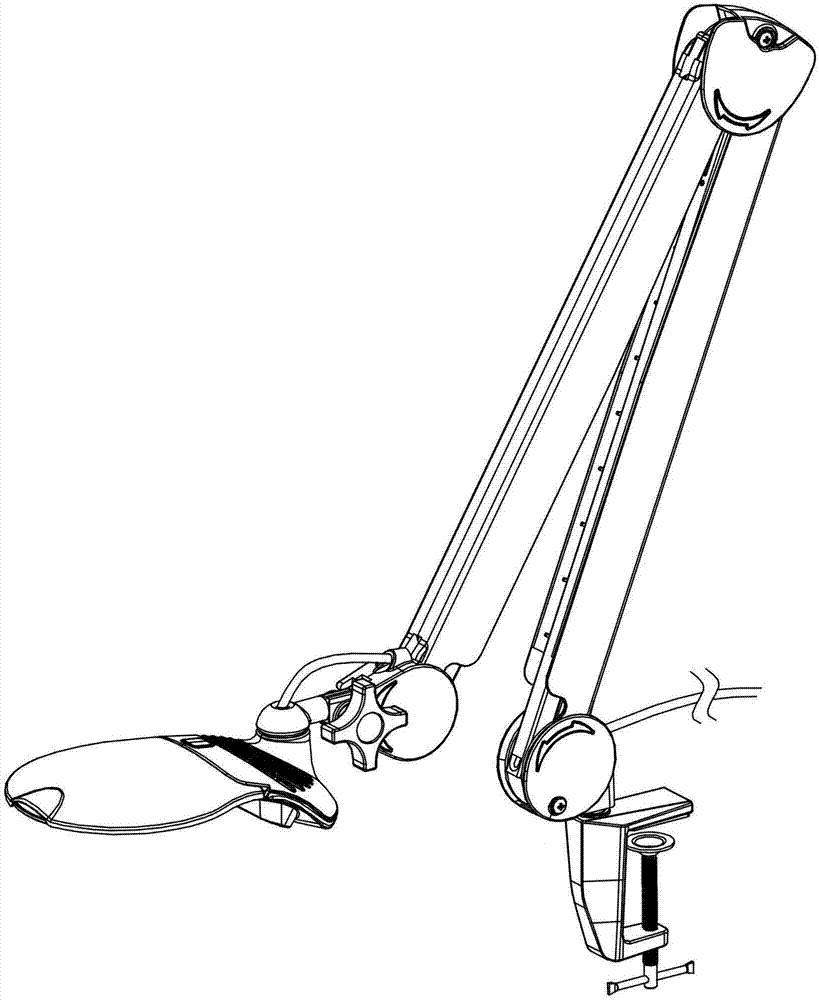
  • Foldable magnifying glass lamp
  • Foldable magnifying glass lamp

Examples


Embodiment Construction

[0020] The present invention will be further described below in conjunction with the accompanying drawings and specific embodiments.

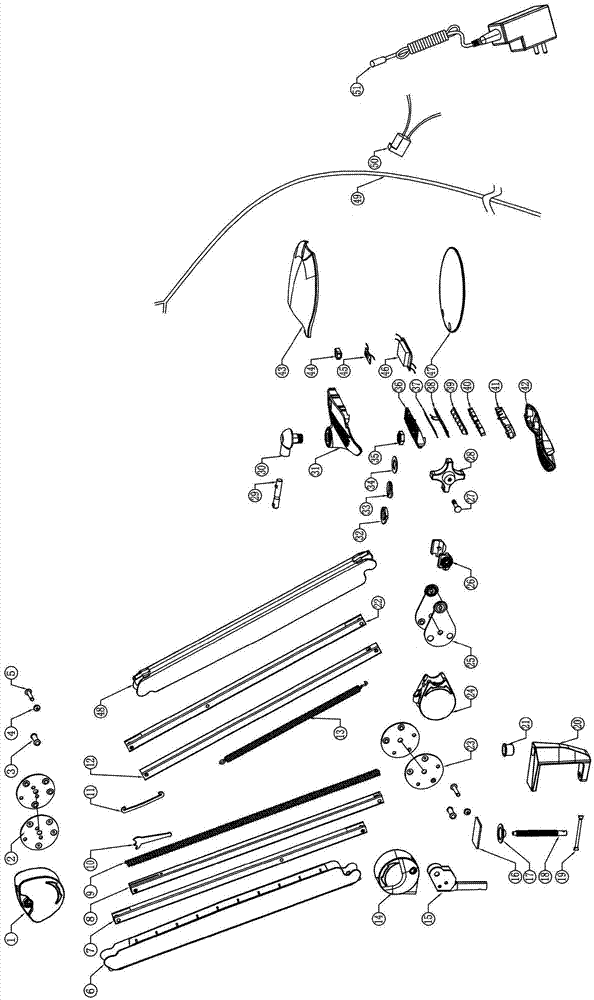
[0021] Such as figure 1 , figure 2 In the described embodiment, a foldable magnifying glass lamp has a lamp head, a support arm and a base clamp. The lamp head includes a head upper shell 31, a head lower shell 42, a lighting assembly and a magnifying glass lens 47, and the lighting assembly is installed on the head. Between the upper shell 31 and the lower shell 42 of the head, the magnifying glass lens 47 is fixed by the upper shell 31 and the lower shell 42 of the head. head and wire 49, the lamp head is connected with one end of the upper rod through the upper chuck, the other end of the upper rod is connected with one end of the lower rod through the middle chuck, and the other end of the lower rod is connected with the base clamp through the lower chuck, and the wire 49 is placed inside the upper pull rod and the lower pressure rod, on...


PUM


Abstract

The invention discloses a foldable magnifying glass lamp. It has a lamp head, an arm and a base clamp. The lamp head includes an upper shell of the head, a lower shell of the head, a lighting assembly and a magnifying glass lens. The lighting assembly is installed between the upper shell of the head and the lower shell of the head. The shell and the lower shell of the head are fixed, and the support arm includes the upper chuck, the upper pull rod, the middle chuck, the lower pressure rod, the lower chuck and the wire, the lamp head, the upper chuck, the upper pull rod, the middle chuck, the lower pressure rod, the lower The chuck and the base clip are connected in turn, the wire is placed inside the upper pull rod and the lower pressure rod, one end of the wire is connected to the lighting component, the other end of the wire is provided with a power jack, and the wire is pluggably connected to the power supply through the power jack. The base clamp includes a clamp frame and a fastening component, and the fastening component is installed on the clamp frame. The beneficial effects of the invention are: long service life; reliable structure, not broken during use; small volume, frameless design; low energy consumption; no pollution, green and environment-friendly.

Description

technical field [0001] The invention relates to a lamp, in particular to a foldable magnifying glass lamp. Background technique [0002] At present, most magnifying glass lamps on the market are composed of a lamp holder, a support rod, and a base. The lamp holder is in the shape of a ring. Beads and magnifying glass lamps can not only illuminate, but also magnify the illuminated objects in a large area or in a local area with high magnification. To sum up, the magnifying glass lamps of the prior art have the following disadvantages: (1) short life, the life of ordinary fluorescent tubes is generally between 8,000 hours and 10,000 hours; (2) easy to damage, ordinary fluorescent tubes are made of glass It is inevitable that the lamp tube will break during transportation and use; (3) The volume is large, and the diameter of the ordinary fluorescent lamp tube is currently at least 12mm, which increases the volume of the entire lamp head, and the line of sight is easily hindere...

Claims


Application Information

Patent Timeline
IPC IPC(8): F21K9/20F21V23/04F21V5/04F21V33/00F21V21/14F21Y115/10
CPCF21V23/04F21V5/04F21V21/14F21V33/00
Inventor 施红卫施红文张钜铨
Owner NINGBO FATO AUTOMATION TECH
Learn More