
Regenerative heat conduction oil heating system provided with built-in electromagnetic heater

A technology for electromagnetic heaters and heating systems, applied in electric heating systems, heating methods, heating systems, etc., can solve the problems of large energy consumption, large floor space, reduced heat conversion efficiency, etc., and achieve long service life and heat. The effect of high conversion efficiency and fast heating speed

Inactive Publication Date: 2017-07-04
LIAONING GUOYUAN ELECTRONICS CO LTD
View PDF11 Cites 3 Cited by
  • Summary
  • Abstract
  • Description
  • Claims
  • Application Information

AI Technical Summary

Problems solved by technology

[0002] At present, civil heating devices include coal-type heating furnaces, gas-fired heating furnaces, and electric heaters. Most of the heating furnaces on the market use coal, gas or oil to heat the water medium, and hot water provides heating for users. Such heating furnaces Low heat exchange efficiency, large energy consumption, small heating area, and after working for a period of time, fouling inside the boiler will further reduce the heat conversion efficiency, block the circulation pipeline, and affect normal heating
[0003] At present, there are also frequency conversion electromagnetic heaters for heating, but the conduction medium is water. Due to the high power, fans are needed for cooling. Adapt to the development trend of heating equipment energy saving and consumption reduction environment

Method used


Image

  • Regenerative heat conduction oil heating system provided with built-in electromagnetic heater
  • Regenerative heat conduction oil heating system provided with built-in electromagnetic heater

Examples


Embodiment Construction

[0017] The present invention will be further described below in conjunction with drawings and embodiments.

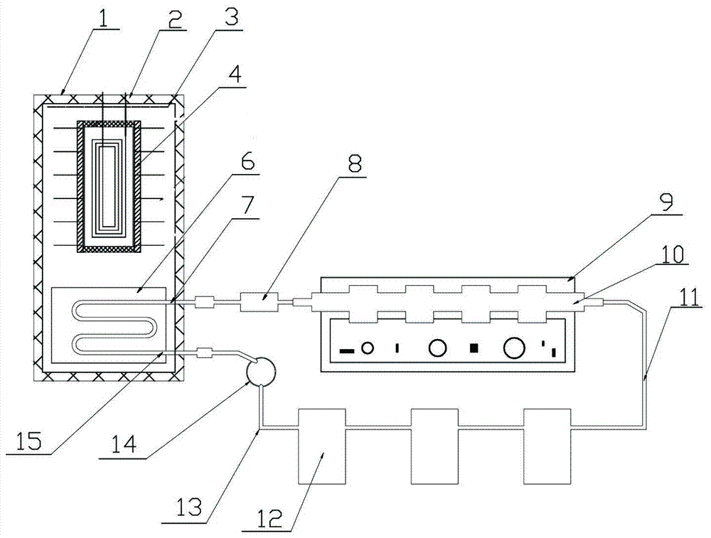
[0018] Such as figure 1 and figure 2 As shown, a heat storage type heat transfer oil heating system with a built-in electromagnetic heater of the present invention includes a heat storage oil tank 1 with an insulating layer 2, an electromagnetic heater, a heating device 12 and an electric control box, and is characterized in that:

[0019] Described electromagnetic heater is made up of main electromagnetic heater 4, auxiliary electromagnetic heater 8,

[0020] The main electromagnetic heater 4 is arranged in the heat storage oil tank 1 with an insulation layer, and an oil-water heat exchanger 6 is also arranged in the heat storage temperature oil tank 1 with an insulation layer;

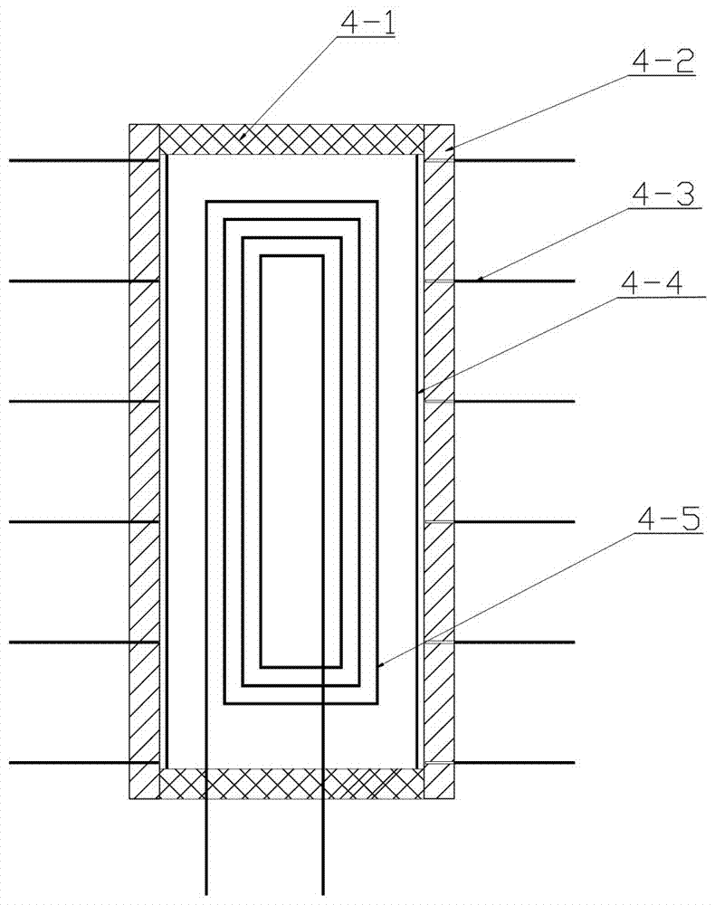
[0021] The main electromagnetic heater includes a magnetically conductive housing 4-2, a non-magnetically conductive support member 4-1 and an electromagnetic induction coil 4-5 arranged at...


PUM


Abstract

The invention explicitly relates to a regenerative heat conduction oil heating system provided with a built-in electromagnetic heater. The system comprises a regenerative oil tank provided with a thermal insulation layer, the electromagnetic heater, a heating device and an electric cabinet; the regenerative heat conduction oil heating system is characterized in that the electromagnetic heater consists of a main electromagnetic heater and an auxiliary electromagnetic heater, wherein the main electromagnetic heater comprises a magnetic conductive shell, non-magnetic conductive support pieces respectively arranged at the two ends of the magnetic conductive shell, and an electromagnetic induction coil; the electric cabinet is internally provided with a water-cooled power tube radiator; an electromagnetic induction coil and a circulating water pump which are arranged on the auxiliary electromagnetic heater are respectively and electrically connected with the electric cabinet. Compared with the prior art, the regenerative heat conduction oil heating system has the beneficial effects that by adopting an electromagnetic heating technology, the system is environmentally-friendly, rapid in heating speed and high in thermal conversion efficiency, has the effective heat utilization rate of 98%, and can save energy by 30% or more compared with a coal-fired boiler; furthermore, in a heating process, the regenerative heat conduction oil heating system not only does not produce water scale, but also is long in service life, saves energy and reduced consumption, and is enabled to be safe and reliable.

Description

technical field [0001] The invention relates to the field of electromagnetic heating and heating, in particular to a heat-storage heat-conducting oil heating system with a built-in electromagnetic heater. Background technique [0002] At present, civil heating devices include coal-type heating furnaces, gas-fired heating furnaces, and electric heaters. Most of the heating furnaces on the market use coal, gas or oil to heat the water medium, and hot water provides heating for users. Such heating furnaces The heat exchange efficiency is low, the energy consumption is large, the heating area is small, and after working for a period of time, the internal scaling of the boiler will further reduce the heat conversion efficiency, block the circulation pipeline, and affect normal heating. [0003] At present, there are also frequency conversion electromagnetic heaters for heating, but the conduction medium is water. Due to the high power, fans are needed for cooling. Adapt to the d...

Claims


Application Information

Patent Timeline
IPC IPC(8): F24D13/04F24D19/10
CPCF24D13/04F24D19/1096F24D2200/08
Inventor 田翰辰王彦国
Owner LIAONING GUOYUAN ELECTRONICS CO LTD
Features
  • Generate Ideas
  • Intellectual Property
  • Life Sciences
  • Materials
  • Tech Scout
  • Unparalleled Data Quality
  • Higher Quality Content
  • 60% Fewer Hallucinations
Learn More