Method for diagnosis of ultra-short pulse focusing field spatial and temporal distribution characteristics

A technology of space-time distribution, ultra-short pulse, applied in instruments and other directions, can solve problems such as affecting results

Active Publication Date: 2017-07-04
LASER FUSION RES CENT CHINA ACAD OF ENG PHYSICS
View PDF8 Cites 3 Cited by
  • Summary
  • Abstract
  • Description
  • Claims
  • Application Information

AI Technical Summary

Problems solved by technology

However, due to the existence of large-aperture lenses (for spatial filtering and image transfer) in ultra-short and ultra-intense laser systems, the spatio-temporal distribution of the final focused field is far from ideal, which will significantly affect strong-field physics or high energy density Therefore, obtaining the actual spatio-temporal distribution information of the focusing field of the ultrashort pulse laser device is undoubtedly of great significance for the pre-design of the corresponding physical experiment and the understanding of the image of the physical experiment
[0003] So far, no technique has been used to diagnose the spatiotemporal distribution of the focal field

Method used


Image

  • Method for diagnosis of ultra-short pulse focusing field spatial and temporal distribution characteristics
  • Method for diagnosis of ultra-short pulse focusing field spatial and temporal distribution characteristics
  • Method for diagnosis of ultra-short pulse focusing field spatial and temporal distribution characteristics

Examples


Embodiment

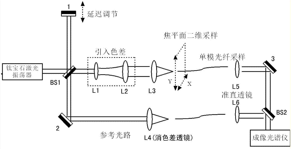
[0025] see figure 1 ,

[0026] The transmitted light of the ultrashort pulse laser generated by the titanium sapphire laser oscillator is split by the first half-mirror BS1 as the signal light, and the beam is expanded by the lens group, namely the first lens L1 and the second lens L2, and then the third lens is used L3 is focused, the focus field is sampled by the single-mode optical fiber installed on the micro-displacement platform, output through the first collimator lens L5, and finally reflected by the third square mirror 3 and transmitted by the second half-mirror BS2 , incident into the imaging spectrometer;

[0027] The ultrashort pulse laser generated by the titanium sapphire laser oscillator is reflected by the first half-mirror BS1 as a reference light, which is reflected by the first plane mirror 1 and returns to the first half-mirror BS1 in the same way. , and then reflected by the second plane mirror 2 and focused by the achromatic lens L4 to the single-mode o...


PUM


Abstract

The present invention discloses a method for diagnosis of ultra-short pulse focusing field spatial and temporal distribution characteristics, belonging to the ultra-short laser technology field. The transmitted light of light splitting of ultra-short pulse laser through a half transparent and half reflecting mirror is taken as signal light, the light reflected by the half transparent and half reflecting mirror is taken as reference light, the signal light and the reference light perform each optical path imaging to obtain interference pattern, time delay of the signal pulse at the sampling position relative to the reference light is obtained according to the interference pattern, and the two-dimensional scanning of a micrometric displacement platform is employed to obtain sampling on the horizontal and vertical directions so as to obtain spatial and temporal distribution of a signal light focusing field on the horizontal and vertical directions. The method is the only technology capable of performing focusing field spatial and temporal distribution characteristic diagnosis at present so as to provide help for design of corresponding physical experiment in advance and the understanding for the images of the physical experiment.

Description

technical field [0001] The invention belongs to the technical field of ultrashort and ultraintense lasers, and in particular relates to a method for diagnosing the temporal and spatial distribution characteristics of an ultrashort pulse focusing field. Background technique [0002] At present, ultra-intense and ultra-short pulse laser has become an important tool for the research of strong field physics and high energy density physics. Researchers can obtain extremely high electric field and power density by focusing short pulse laser. However, due to the existence of large-aperture lenses (for spatial filtering and image transfer) in ultra-short and ultra-intense laser systems, the spatio-temporal distribution of the final focused field is far from ideal, which will significantly affect strong-field physics or high energy density Therefore, obtaining the actual spatiotemporal distribution information of the focusing field of the ultrashort pulse laser device is undoubtedly ...

Claims


Application Information

Patent Timeline
Patent Type & Authority Applications(China)
IPC IPC(8): G01J11/00
CPCG01J11/00
Inventor 左言磊曾小明周凯南王逍吴朝晖王晓东黄小军谢娜母杰蒋东镔周松郭仪孙立黄征粟敬钦
Owner LASER FUSION RES CENT CHINA ACAD OF ENG PHYSICS
Why Eureka
Try Eureka