Digital oscilloscope and multichannel signal synchronization method thereof

A digital oscilloscope and channel technology, applied in the direction of digital variable display, digital variable/waveform display, instruments, etc., can solve the problems of inconsistent FIFO depth and different data path delays, so as to avoid different path delays and reduce depth requirements. Effect

Inactive Publication Date: 2017-07-04
SHENZHEN CITY SIGLENT TECH
View PDF5 Cites 6 Cited by
  • Summary
  • Abstract
  • Description
  • Claims
  • Application Information

AI Technical Summary

Problems solved by technology

[0004] In the existing technical solution, IP uses FIFO to adjust the delay of each serial channel to achieve the purpose of synchronous alignment between channels. However, the depth of FIFO may be inconsistent each time the power is turned on, which will cause data path delay. Different

Method used


Image

  • Digital oscilloscope and multichannel signal synchronization method thereof
  • Digital oscilloscope and multichannel signal synchronization method thereof
  • Digital oscilloscope and multichannel signal synchronization method thereof

Examples


Embodiment 1

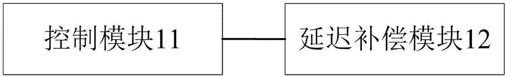
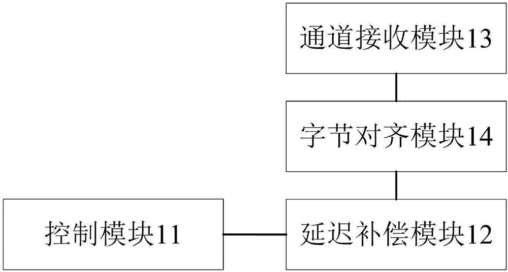
[0046] refer to figure 1 , shows a structural block diagram of a digital oscilloscope in the present invention, the digital oscilloscope includes: a control module 11 and a delay compensation module 12; wherein,

[0047] The control module 11 is used to determine the delay deviation of the data in each receiving channel before the data in each receiving channel is subjected to delay compensation in the delay compensation module, and divide each receiving channel according to the delay deviation of the data in each receiving channel Delays of other receiving channels except the main channel are synchronized to the main channel to achieve clock alignment between channels;

[0048] The delay compensation module 12 is configured to perform delay compensation on received data.

[0049] In actual implementation, the delay compensation module may be a FIFO module.

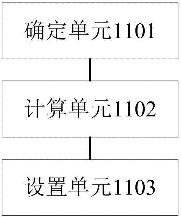
[0050] Specifically, such as figure 2 As shown, the control module 11 includes: a determination unit 1101, a calcul...

Embodiment 2

[0067] refer to Figure 7 , Embodiment 2 of the present invention provides a multi-channel signal synchronization method for a digital oscilloscope, characterized in that the method includes:

[0068] Step 701: Determine the delay deviation of data in each receiving channel, and synchronize the delays of receiving channels of each receiving channel except the main channel to the main channel according to the delay deviation of data in each receiving channel, so as to realize inter-channel clock alignment;

[0069] Specifically, such as Figure 7 As shown, the delay synchronization of each receiving channel except the main channel to the main channel according to the delay deviation of the data in each receiving channel includes the following processing steps:

[0070] S801. Determine one of the multiple receiving channels as the master receiving channel, and determine the other receiving channels as slave receiving channels;

[0071] S802. Calculate the delay deviation of d...


PUM


Abstract

The embodiment of the invention provides a multichannel signal synchronization method of a digital oscilloscope. The multichannel signal synchronization method comprises the steps of firstly determining the delay deviation of data in each receiving channel, synchronizing the delay of all receiving channels except for a main channel to the main channel according to the delay deviation of data in each receiving channel so as to realize clock alignment of the channels, and then performing delay compensation on the data in each receiving channel. based on the scheme, the other channels are synchronized to the main channel before delay compensation is performed on the data, so that depth requirements for FIFO (First In First Out) are greatly reduced in delay compensation for the data, thus delay compensation for the data is enabled not to be restricted by the depth of FIFO, and problem that the data is different in path delay is also avoided. The embodiment of the invention further provides a digital oscilloscope.

Description

technical field [0001] The invention relates to the technical field of digital oscilloscopes, in particular to a digital oscilloscope and a multi-channel signal synchronization method thereof. Background technique [0002] A digital oscilloscope is an instrument that visually displays the waveform of a signal changing with time. It is a high-performance signal characteristic testing instrument that integrates a series of technologies such as data acquisition, A / D conversion, and software programming. [0003] With the development of electronic industry technology, the sampling rate of the analog-to-digital converter (ADC) in the digital oscilloscope is getting higher and higher. The speed of transmitting sampling points using the traditional parallel interface has reached a bottleneck, and it is replaced by a faster serial interface. row interface. The analog-to-digital converter (ADC) converts the sampled data into a multi-channel high-speed serial signal, passes through t...

Claims


Application Information

Patent Timeline
Patent Type & Authority Applications(China)
IPC IPC(8): G01R13/02
CPCG01R13/0254
Inventor 李振军吴乾科
Owner SHENZHEN CITY SIGLENT TECH
Why Eureka
Try Eureka