System and method for bar flying shearing optimization control based on machine vision

An optimized control and machine vision technology, applied in general control systems, control/regulation systems, adaptive control, etc., can solve problems such as reducing output, elbows, monitoring, etc., to achieve the effect of convenient engineering implementation and simple system structure

Active Publication Date: 2017-07-04
HUATIAN ENG & TECH CORP MCC +1
View PDF10 Cites 3 Cited by
  • Summary
  • Abstract
  • Description
  • Claims
  • Application Information

AI Technical Summary

Problems solved by technology

[0003] In the traditional shearing process, after the steps of the shearing action are predefined, the flying shears will work according to the predefined action, but there is no basic monitoring of the shearing effect. In the bar production workshop, it is easy to cause slender billets Various problems such as elbows, extrusion or rough sections
If the cutting effect of the flying shear is not good, the finished product needs to be processed, resulting in waste of materials and reduced output

Method used


Image

  • System and method for bar flying shearing optimization control based on machine vision

Examples


Embodiment 1

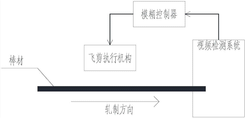
[0035] like figure 1 As shown, this embodiment provides a machine vision-based optimal control system for bar flying shear shearing, including an image acquisition subsystem, a fuzzy controller, and a flying shear adjustment subsystem;

[0036] The image acquisition subsystem includes a plurality of cameras arranged behind the flying shears and a light source matched with each of the cameras, and each of the cameras is connected in communication with the image processing module;

[0037] The fuzzy controller is in communication connection with the image processing module, and is used to receive the image information processed by the image processing module, generate a flying shear adjustment decision, and transmit the flying shear adjustment decision to the flying shear adjustment subsystem ;

[0038] The flying shear adjustment subsystem includes a control mechanism for controlling the flying shear driving mechanism or the transmission mechanism, and is used to adjust the mo...

Embodiment 2

[0049] The difference between this embodiment and Embodiment 1 is that the flying shear adjustment subsystem is controlled and connected to the continuously variable gearbox, and the input shaft and the output shaft of the continuously variable gearbox are respectively connected with the driving device of the flying shear cutting edge. Connect with the flying shears.

[0050] This embodiment can also adjust the motion trajectory and torque of the flying shears by adjusting the continuously variable gearbox, and can achieve the same adjustment effect as the first embodiment. In this embodiment, those skilled in the art can adjust the continuously variable transmission according to the control strategy according to the prior art.

Embodiment 3

[0052] The present embodiment provides a machine vision-based method for optimizing the shearing of bar flying shears, comprising the following steps:

[0053] S1 collects and saves the control image when there is no bar in the flying shear area;

[0054] S2 collects the bar image after shearing by the flying shears, compares the bar image with the control image, and obtains the bar image with the background removed;

[0055] S3 calculates the bending degree and section quality of the bar image with the background removed;

[0056] S4 inputs the degree of curvature and the quality of the section to the fuzzy controller, and the fuzzy controller generates an adjustment decision according to the degree of curvature and the quality of the section, and transmits the adjustment decision to the flying shear adjustment subsystem;

[0057] The S5 flying shear adjustment subsystem adjusts the flying shear according to the adjustment decision;

[0058] The flying shear adjusted by S6 cu...


PUM


Abstract

The present invention discloses a system for bar flying shearing optimization control based on machine vision. The system comprises an image collection subsystem, a fuzzy controller and a flying shear regulation subsystem. The image collection subsystem comprises a plurality of cameras arranged at the rear portions of flying shears and light sources respectively matching each camera, and each camera is in communication connection with the image processing module; the fuzzy controller is in communication connection with the image processing module and is configured to receive image information completely processed by the image processing module, generate a flying shear regulation decision and transmit the flying shear regulation decision to the flying shear regulation subsystem; and the flying shear regulation subsystem comprises a control mechanism configured to control a flying shear driving mechanism or transmission mechanism and regulate the movement locus and the moment of the flying shearing. The work of the flying shears changes an open loop mode to a closed-loop work mode to realize the online optimization of the bar shearing work.

Description

technical field [0001] The invention relates to an optimal control system and method for bar flying shear shearing based on machine vision. Background technique [0002] Flying shears are often used in steel rolling, papermaking and other production lines. In the bar shop, it is placed at the back of the rolling line and cuts the rolled stock to length or just the head and tail. The widespread use of flying shears is conducive to the rapid development of high-speed and continuous steel rolling production. Therefore, it is one of the important links in the development of rolling steel production. [0003] In the traditional shearing process, after the steps of the shearing action are predefined, the flying shears work according to the predefined actions, but lack of basic monitoring of the shearing effect, in the bar production workshop, it is easy to cause slender blanks Elbow, extrusion or rough section and other problems. If the shearing effect of the flying shear is n...

Claims


Application Information

Patent Timeline
Patent Type & Authority Applications(China)
IPC IPC(8): G05B13/04
CPCG05B13/042
Inventor 方田桂峰朱凤泉彭获锋
Owner HUATIAN ENG & TECH CORP MCC
Why Eureka
Try Eureka