Organic light-emitting device

An electroluminescent device and electroluminescent technology, which can be applied to electric solid devices, electrical components, semiconductor devices, etc., can solve problems such as low efficiency, and achieve the effect of reducing the efficiency roll-off problem.

Active Publication Date: 2017-07-04
KUNSHAN NEW FLAT PANEL DISPLAY TECH CENT
View PDF8 Cites 35 Cited by
  • Summary
  • Abstract
  • Description
  • Claims
  • Application Information

AI Technical Summary

Problems solved by technology

[0006] For this reason, the technical problem to be solved by the present invention is that the light-emitting host material in the prior art has a lower triplet T 1 And the smaller energy gap Eg (the energy level difference between HOMO and LUMO) leads to the problem of low efficiency of exciton recombination, and then provides an organic electroluminescent device, using thermally activated delayed fluorescent material as the host material limit The recombination of excitons in the light-emitting region effectively suppresses the efficiency roll-off phenomenon, and the device efficiency is increased to 13% to 18%.

Method used


Image

  • Organic light-emitting device
  • Organic light-emitting device
  • Organic light-emitting device

Examples


Embodiment 1

[0086] The device structure of the present embodiment 1 is as follows:

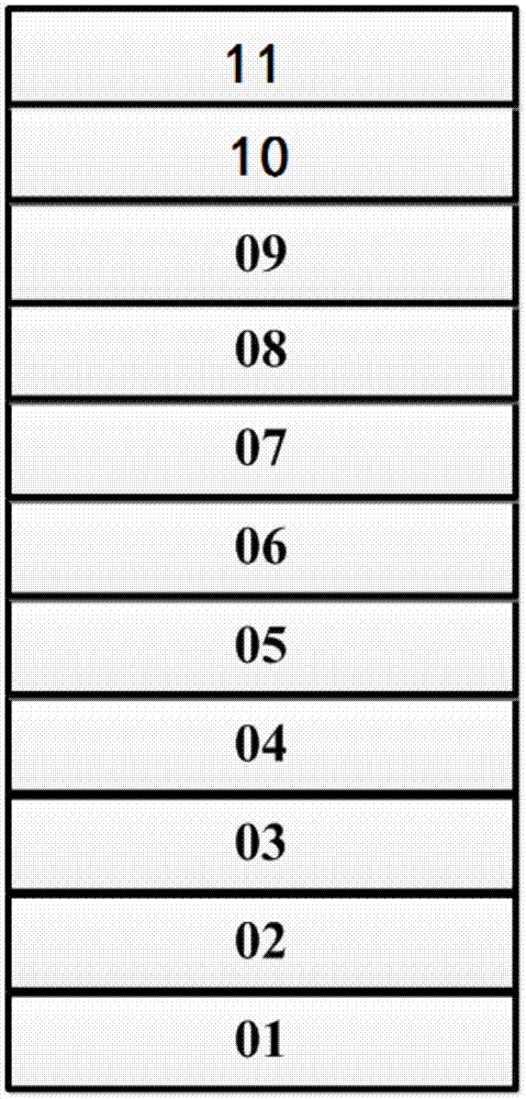
[0087] ITO / HATCN[5nm] / NPB[30nm] / HTL[10nm] / Formula (1-24): CBP:1wt%DCJTB[30nm] / ETL[40nm] / LiF[0.5nm] / Al[150nm]

[0088] The device of the present embodiment 1 is composed of substrate, anode layer (ITO), hole injection layer (HATCN), first hole transport layer (NPB), second hole transport layer HTL, light emitting layer (formula (1-24) ): CBP: 1wt% DCJTB), electron transport layer (ETL), insulating buffer layer (LiF), cathode layer (Al), the main material of the light-emitting layer is the thermally activated sensitized fluorescent material shown in formula (1-24) and The hole-transporting material is composed of CBP, and the mass ratio of the two is 1:9. The first triplet state of the hole transport layer material is higher than the first singlet state of the exciplex produced by the host material, and the first triplet state of the electron transport layer material is higher than the first singlet state ...

Embodiment 2

[0096] The device structure of the present embodiment 2 is as follows:

[0097] ITO / HATCN[5nm] / NPB[30nm] / HTL[10nm] / TCTA:CzTrz:10wt%DMQA[30nm] / ETL[40nm] / LiF[0.5nm] / Al[150nm]

[0098] The device of present embodiment 2 is by substrate, anode layer (ITO), hole injection layer (HATCN), first hole transport layer (NPB), second hole transport layer (HTL), light-emitting layer (TCTA: CzTrz: 10wt% DMQA), electron transport layer (ETL), insulating buffer layer (LiF), cathode layer (Al), the main material of the light-emitting layer is composed of hole transport material TCTA and electron transport material CzTrz, the mass ratio of the two It is 2:3. The first triplet state of the hole transport layer material is higher than the first singlet state of the exciplex produced by the host material, and the first triplet state of the electron transport layer material is higher than the first singlet state of the exciplex produced by the host material. State high.

Embodiment 3

[0105] The device structure of the present embodiment 3 is as follows:

[0106] ITO / HATCN[5nm] / NPB[30nm] / HTL[10nm] / Formula (1-9): PPT:10wt%BCzVBi[30nm] / ETL[40nm] / LiF[0.5nm] / Al[150nm]

[0107] The device of the present embodiment 3 consists of a substrate, an anode layer (ITO), a hole injection layer (HATCN), a first hole transport layer (NPB), a second hole transport layer (HTL), a light-emitting layer (formula (1 -9): PPT: 10wt% BczVBi), electron transport layer (ETL), insulating buffer layer (LiF), cathode layer (Al), the main material of the light-emitting layer is a hole transport material formula (1-9) and electron The transmission type material is composed of PPT, and the mass ratio of the two is 9:1. The first triplet state of the hole transport layer material is higher than the first singlet state of the exciplex produced by the host material, and the first triplet state of the electron transport layer material is higher than the first singlet state of the exciplex pr...


PUM


Abstract

The invention relates to an organic light-emitting device. The main body materials of a light-emitting layer comprise materials with hole transfer capability and electron transfer capability; a triplet state T1H of at least one kind of main body material is greater than or equal to a singlet state S1F of a fluorescent dye; a triplet state energy level T1H of a CT excited state of at least one kind material of the main body materials is higher than a singlet state energy level S1H of an n-<pi> excited state, and T1H-S1H is less than or equal to 0.3eV; or the triplet state energy level T1H of the CT excited state of at least one kind of material of the main body materials is higher than a triplet state energy level S1H of the n-<pi> excited state, and T1H-S1H is greater than or equal to 1eV; in addition, the difference value between the second triplet state energy level of the n-<pi> excited state of the main body materials, and the first singlet state energy level of the CT excited state is -0.1eV to 0.1eV; and the triplet states T1 of organic functional layer materials adjacent to the light emitting layer are all higher than the singlet state S1H of the main body materials of the light emitting layer. By adopting a thermal activation delayed florescence material as the main body materials, so that recombination of excitons in the light-emitting region is limited, a phenomenon of efficiency roll-off is effectively suppressed, and the device efficiency can be improved to 13-18%.

Description

technical field [0001] The invention relates to the technical field of organic electroluminescent devices, and specifically designs an organic electroluminescent device using a heat-activated delayed fluorescent material as a main material. Background technique [0002] The light-emitting layer of the organic electroluminescent device OLED is mainly made of all fluorescent materials, all phosphorescent materials or a mixture of fluorescent materials and phosphorescent materials. Among them, the light-emitting layer generally adopts a high triplet T 1 , a host material with a wide energy gap. The organic light-emitting material system includes a fluorescent system and a phosphorescent light-emitting system. A doped system is used, and the fluorescent system only uses the singlet exciton energy. The ideal internal quantum efficiency is only 25%. Low, while the phosphorescent system can utilize singlet and triplet exciton energy at the same time, and the internal quantum effic...

Claims


Application Information

Patent Timeline
Patent Type & Authority Applications(China)
IPC IPC(8): H01L51/50
CPCH10K85/324H10K50/121H10K50/11H10K2101/40H10K2101/10
Inventor 赵菲
Owner KUNSHAN NEW FLAT PANEL DISPLAY TECH CENT
Why Eureka
Try Eureka