Al technical title is built by PatSnap Al team. It summarizes the technical point description of the patent document.
A technology of riveting presses and products, which is applied in the field of automatic riveting presses for disc products, can solve the problems of backward production methods, large safety hazards, and low production efficiency, and achieve no safety hazards, small noise hazards, and improved production efficiency Effect
Active Publication Date: 2017-07-07
摩丁普信热能技术(江苏)有限公司
View PDF5 Cites 2 Cited by
Summary
Abstract
Description
Claims
Application Information
AI Technical Summary
This helps you quickly interpret patents by identifying the three key elements:
Problems solved by technology
Method used
Benefits of technology
Problems solved by technology
[0003] The technical problem to be solved by the present invention is to provide an automatic riveting press device for disc products, which solves the problems of backward production methods, low production efficiency, large safety hazards, and large noise pollution in traditional disc chip assembly riveting operations
Method used
Image
Click on the blue label to locate the original text in one second.
Reading with bidirectional positioning of images and text.
Examples
Embodiment Construction
[0024] The preferred embodiments of the present invention are given below in conjunction with the accompanying drawings to describe the technical solution of the present invention in detail.
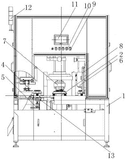
[0025] Such as figure 1 As shown, the disc product automatic riveting press device of the present invention includes a frame assembly 1, a turntable assembly 2, a press assembly 3, an automatic blanking suction cup assembly 4, a discharge jack assembly 5, a primary riveting upper and lower mold assembly 6, Secondary riveting upper and lower die assembly 7, safety grating 8, emergency button 9, start button 10, touch screen 11, tricolor lamp 12, proximity switch 13, turntable assembly 2, primary riveting upper and lower die assembly 6, safety grating 8 , the secondary riveting upper and lower mold assembly 7, the automatic blanking suction cup assembly 4, and the discharge jacking assembly 5 are all installed inside the frame assembly 1, the proximity switch 13 is on the right side of the...
PUM
Abstract
The invention discloses an automatic disc product rivet machine device. The automatic disc product rivet machine device comprises a frame assembly, a rotating disc assembly, a pressing machine assembly, an automatic discharging suction cup assembly, a discharging jacking assembly, a primary rivet mold feeding and discharging assembly, a secondary rivet mold feeding and discharging assembly, a safety grating, an emergency button, a starting button, a touch screen, a three-color lamp, an approach switch and a rotating disc assembly; the primary rivet mold feeding and discharging assembly, the safety grating, the secondary rivet mold feeding and discharging assembly, the automatic discharging suction cup assembly and the discharging jacking assembly are mounted in the frame assembly, the approach switch is arranged on the right side of the discharging jacking assembly, the rotating disc assembly is located below the primary rivet mold feeding and discharging assembly, the secondary rivet mold feeding and discharging assembly and the automatic discharging suction cup assembly, the emergency button, the start button and the touch screen are all arranged outside the frame assembly, and the three-color lamp is located at the top end of the side face of the frame assembly. Two automatic rivet working procedures are adopted to be finished at one time, rivet time is shortened, work time is shortened, and labor intensity is reduced.
Description
technical field [0001] The invention relates to a riveting press device, in particular to an automatic riveting press device for disc products. Background technique [0002] The disc chip assembly is one of the important parts in the disc oil cooler, and its entire riveting process needs to go through four processes of feeding, crimping, riveting and unloading. The existing disc chip assembly riveting work mainly uses experienced operators to use 10T, 16T punches and corresponding molds to manually feed materials, and manually operate the punches to complete the crimping and riveting process of the chip assembly. This kind of operation process requires two operators to carry out the two processes of crimping and riveting respectively, and the average daily qualified output of the two operators is about 2,000 pieces in 8 hours. The traditional riveting operation mode mainly has the following shortcomings: backward production methods, low output, and low production efficiency...
Claims
Application Information
Patent Timeline
Application Date:The date an application was filed.
Publication Date:The date a patent or application was officially published.
First Publication Date:The earliest publication date of a patent with the same application number.
Issue Date:Publication date of the patent grant document.
PCT Entry Date:The Entry date of PCT National Phase.
Estimated Expiry Date:The statutory expiry date of a patent right according to the Patent Law, and it is the longest term of protection that the patent right can achieve without the termination of the patent right due to other reasons(Term extension factor has been taken into account ).
Invalid Date:Actual expiry date is based on effective date or publication date of legal transaction data of invalid patent.