Melt cutting grinding material jet flow equipment for pre-heat mixed grinding material jet flow based on function of arc heat effect

A pre-mixed abrasive and abrasive jet technology, applied in the used abrasive processing device, abrasive feeding device, abrasive and other directions, can solve the problem that the working pressure of cutting steel cannot be reduced, the cutting quality of the cutting end face of the target cannot be improved, and it is difficult to Ensure that the inclined hot melt nozzle and cutting nozzle are within the appropriate target distance range, so as to reduce the finishing process, reduce the processing cost and improve the cutting quality.

Active Publication Date: 2017-07-07
ANHUI UNIV OF SCI & TECH
View PDF5 Cites 5 Cited by
  • Summary
  • Abstract
  • Description
  • Claims
  • Application Information

AI Technical Summary

Problems solved by technology

[0003] However, the existing water jet equipment cannot reduce the working pressure of cutting steel, improve the cutting quality of the target cutting end face, reduce the subsequent finishing process, and reduce the processing cost. Some water jet equipment cannot adjust the relative position of the adjustment plate and the adjustment seat. , it is difficult to ensure that the inclined hot-melt nozzle is directly in front of the trajectory of the cutting nozzle, and it is impossible to ensure that the target is under the effect of arc heat; some water jet equipment cannot limit the movement track of the adjustment plate and the adjustment seat; it is difficult to ensure that the inclined hot-melt nozzle and cutting nozzles are within the proper target distance range

Method used


Image

  • Melt cutting grinding material jet flow equipment for pre-heat mixed grinding material jet flow based on function of arc heat effect
  • Melt cutting grinding material jet flow equipment for pre-heat mixed grinding material jet flow based on function of arc heat effect
  • Melt cutting grinding material jet flow equipment for pre-heat mixed grinding material jet flow based on function of arc heat effect

Examples


Embodiment Construction

[0019] In order to make the technical means, creative features, objectives and effects achieved by the present invention easy to understand, the present invention will be further described below in conjunction with specific embodiments and illustrations.

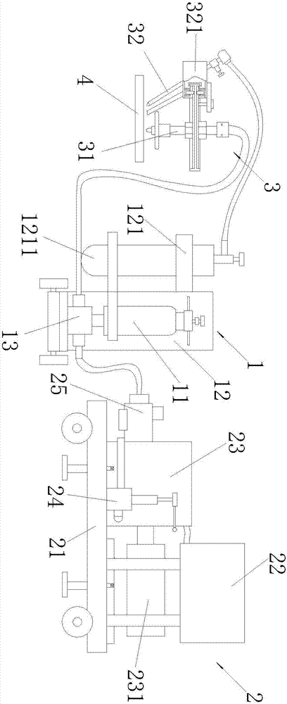
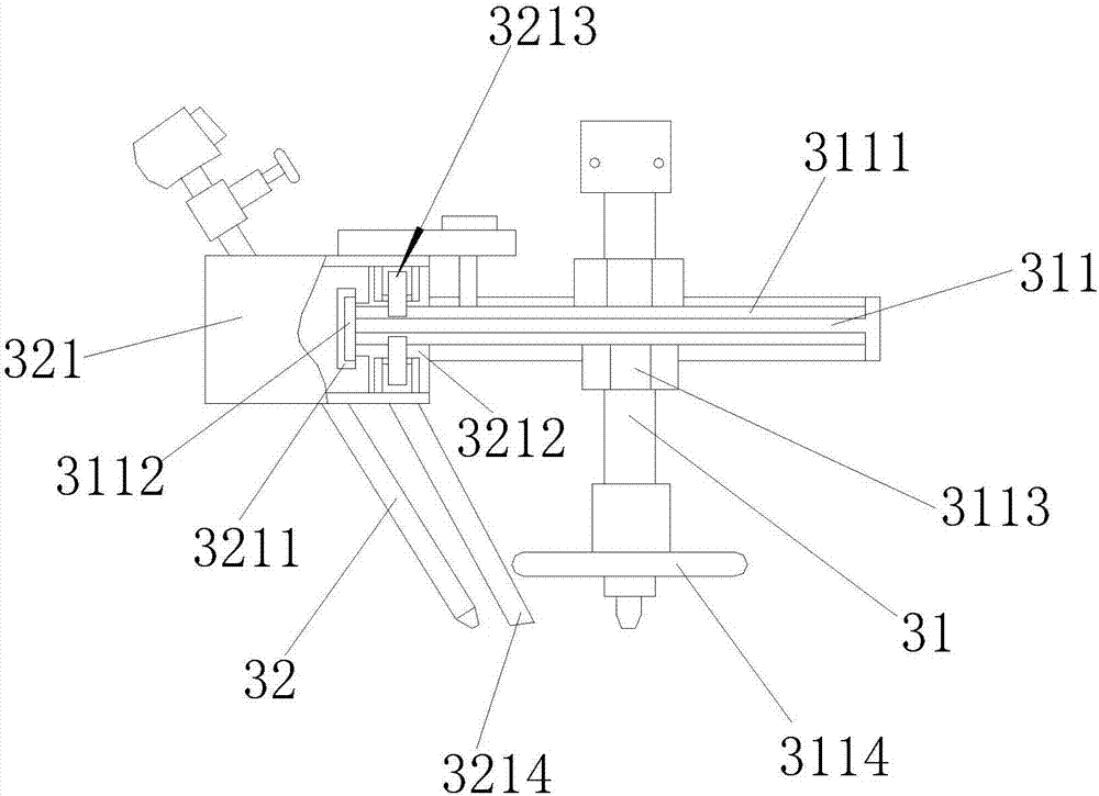
[0020] Such as figure 1 , figure 2 , image 3 , Figure 4 and Figure 5 As shown, the abrasive jet equipment for thermal pre-mixed abrasive jet melting and cutting based on arc heat effect includes a portable generating device 1, a high-pressure pump station 2 and a target 4, and also includes a thermal fusion cutting device 3. The melting cutting device 3 comprises a cutting nozzle 31 and an inclined hot-melt nozzle 32, the cutting nozzle 31 is vertically arranged, and the middle part of the cutting nozzle 31 is threadedly equipped with an adjusting plate 311, and the outer circle of the adjusting plate 311 is An annular ring gear 3111 and an annular limit retaining ring 3112 are provided, and the annular ring gear 311...


PUM


Abstract

The invention discloses melt cutting grinding material jet flow equipment for a pre-heat mixed grinding material jet flow based on the function of the arc heat effect. The equipment comprises a portable generator, a high-pressure pumping station, a target and a hot melt cutting device. The hot melt cutting device comprises a cutting nozzle and tilting hot melt nozzles; the cutting nozzle is arranged vertically; an adjusting fixing disc is mounted in the middle of the cutting nozzle through a thread; annular gear rings and annular limit blocking rings are arranged at the outer circle of the adjusting fixing disc; and the annular gear rings are further symmetrically distributed on the two sides of the adjusting fixing disc and located on the inner sides of the annular limit blocking rings. Adjusting fixing nuts are mounted on the two sides of the adjusting fixing disc correspondingly; and further mounted in the middle of the cutting nozzle. It can be realized that a position to be cut of the target is always under the function of the arc heat effect, the working pressure of steel cutting is greatly reduced, the cutting quality of the target cutting end face is obviously improved, and it is guaranteed that the target to be cut is under the function of the arc heat effect.

Description

technical field [0001] The invention relates to the technical field of abrasive water jet mechanical equipment design, in particular to a thermally pre-mixed abrasive jet melting and cutting abrasive jet equipment under the action of arc heat effect. Background technique [0002] The water jet is a high-speed water stream of different shapes formed by the nozzle, and the flow rate of the jet depends on the pressure drop before and after the nozzle outlet section. Water jetting is the simplest form of energy transformation and application. Usually, the power-driven pump completes a suction and discharge process of water, pumps a certain amount of water to the high-pressure pipeline, and makes it reach the nozzle with a certain amount of energy. The hole diameter of the nozzle is required to be much smaller than that of the high-pressure pipeline, so this certain amount of water reaching the nozzle must be accelerated if it wants to flow out of the nozzle hole. In this way, ...

Claims


Application Information

Patent Timeline
Patent Type & Authority Applications(China)
IPC IPC(8): B24C1/04B24C5/04B24C7/00B24C9/00
CPCB24C1/045B24C5/04B24C7/0007B24C9/00
Inventor 谢淮北张东速王岩
Owner ANHUI UNIV OF SCI & TECH
Why Eureka
Try Eureka