Forced ventilation mechanisms of rotorcraft cabin and rotorcraft

A technology of forced ventilation and rotorcraft, which is applied in the field of aircraft, can solve problems such as the complex structure of the circulation ventilation system, and achieve the effect of direct ventilation, not easy to damage, and not easy to deform

Active Publication Date: 2017-07-07
河北天启通宇航空器材科技发展有限公司
View PDF7 Cites 0 Cited by
  • Summary
  • Abstract
  • Description
  • Claims
  • Application Information

AI Technical Summary

Problems solved by technology

[0007] The purpose of the present invention is to provide a kind of forced ventilation mechanism of the rotor cabin with simple structure and fast ventilation and the rotorcraft provided with the mechanism, so as to solve the technical problem of the complex structure of the circulation ventilation system existing in the prior art

Method used


Image

  • Forced ventilation mechanisms of rotorcraft cabin and rotorcraft
  • Forced ventilation mechanisms of rotorcraft cabin and rotorcraft
  • Forced ventilation mechanisms of rotorcraft cabin and rotorcraft

Examples


Embodiment Construction

[0034] In order to make the purpose, technical solution and advantages of the present invention clearer, the technical solution of the present invention will be described in detail below. Apparently, the described embodiments are only some of the embodiments of the present invention, but not all of them. Based on the embodiments of the present invention, all other implementations obtained by persons of ordinary skill in the art without making creative efforts fall within the protection scope of the present invention.

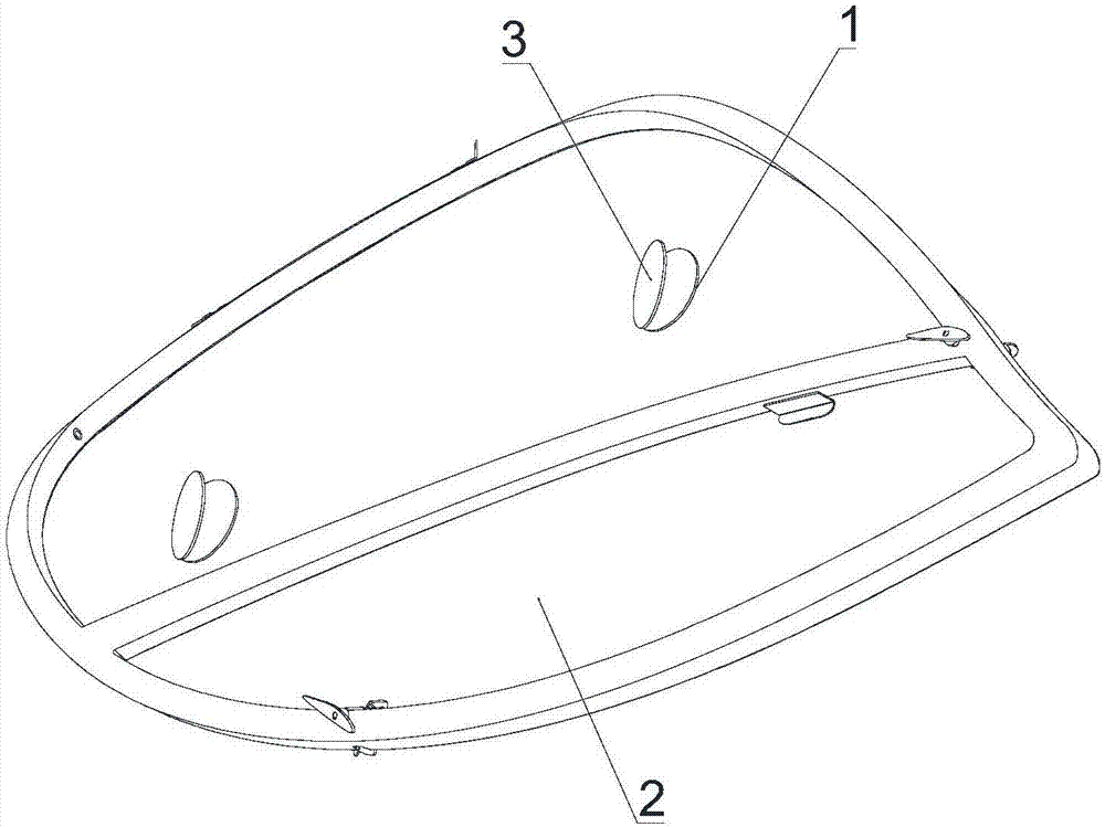
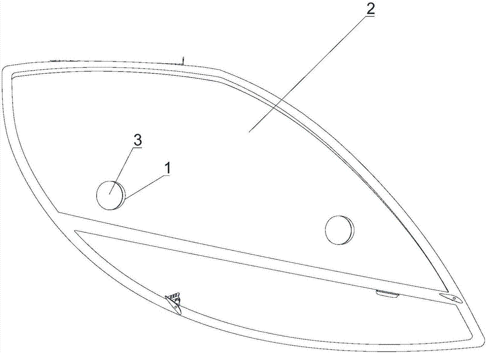
[0035] Such as figure 1 and figure 2 As shown, the invention provides a structure of the forced ventilation mechanism of the rotorcraft cabin door, figure 1 It is a structural schematic diagram of the forced ventilation mechanism when viewed from the outside of the cabin door 2, figure 1 It is a structural schematic diagram of the forced ventilation mechanism when viewed from the inside of the cabin door 2. The forced ventilation mechanism of the rotorcraft...


PUM


Abstract

The invention provides forced ventilation mechanisms of a rotorcraft cabin and a rotorcraft and relates to the technical field of aircrafts. According to the forced ventilation mechanisms, the technical problem that in the prior art, a circulating ventilation system of the rotorcraft is complex in structure is solved. Each forced ventilation mechanism of the rotorcraft cabin comprises a ventilation openings and ventilation opening blocking pieces. The ventilation openings are formed in a cabin door or the cabin wall of the rotorcraft, and the ventilation opening blocking pieces are movably connected to the ventilation openings; the ventilation opening blocking pieces can move to the positions where the ventilation openings are closed and the positions where the ventilation openings are opened; and air in the rotorcraft cabin and air outside the rotorcraft cabin can flow freely through the opened ventilation openings. The ventilation openings are formed in the cabin door or the cabin wall of the rotorcraft to conduct forced ventilation; the structure is simple; the ventilation effect is direct; ventilation is fast; and the ventilation opening blocking pieces are movably arranged on the ventilation openings, so that opening and closing are convenient, and operation is more convenient and faster.

Description

technical field [0001] The invention relates to the technical field of aircraft, in particular to a forced ventilation mechanism for a rotor cabin and a rotorcraft. Background technique [0002] A gyroplane is a rotorcraft that utilizes the relative airflow during forward flight to blow the rotor to rotate to generate lift. Its forward force is directly provided by the engine driving the propeller. It is an aircraft between a helicopter and an airplane, equipped with a rotor and a fixed wing. It has the characteristics of short take-off and landing distance, low-speed and low-altitude flight, simple and lightweight, and easy to conceal, but it cannot take off and land vertically, and cannot hover. It can be used for aerial photography, weapon launch, battlefield reconnaissance, etc. [0003] Gyroplanes and helicopters are exactly the same in appearance, but in essence, gyroplanes and helicopters are two completely different aircrafts. Cyclogyro is actually a kind of airc...

Claims


Application Information

Patent Timeline
Patent Type & Authority Applications(China)
IPC IPC(8): B64C1/14B64D13/00
CPCB64C1/14B64D13/00
Inventor 宋梓涵
Owner 河北天启通宇航空器材科技发展有限公司
Why Eureka
Try Eureka