Overturning hopper and control method thereof

A technology of hopper and tipping mechanism, which is applied in the direction of tilting and carrying moving vehicles, liquid handling, transporting objects, etc. It can solve the problems of increasing the structural weight of the support system of the lifting drive mechanism of the tipping hopper, and achieve the goal of reducing power and output torque Requirements, the effect of high transmission efficiency

Active Publication Date: 2017-07-07
CISDI ENG CO LTD
View PDF9 Cites 5 Cited by
  • Summary
  • Abstract
  • Description
  • Claims
  • Application Information

AI Technical Summary

Problems solved by technology

However, the larger weight of the equipment will increase the capacity of the tilting hopper lifting drive mechanism and the structural weight of the related support system.

Method used


Image

  • Overturning hopper and control method thereof
  • Overturning hopper and control method thereof
  • Overturning hopper and control method thereof

Examples


Embodiment Construction

[0025] The preferred embodiments of the present invention will be described in detail below with reference to the accompanying drawings.

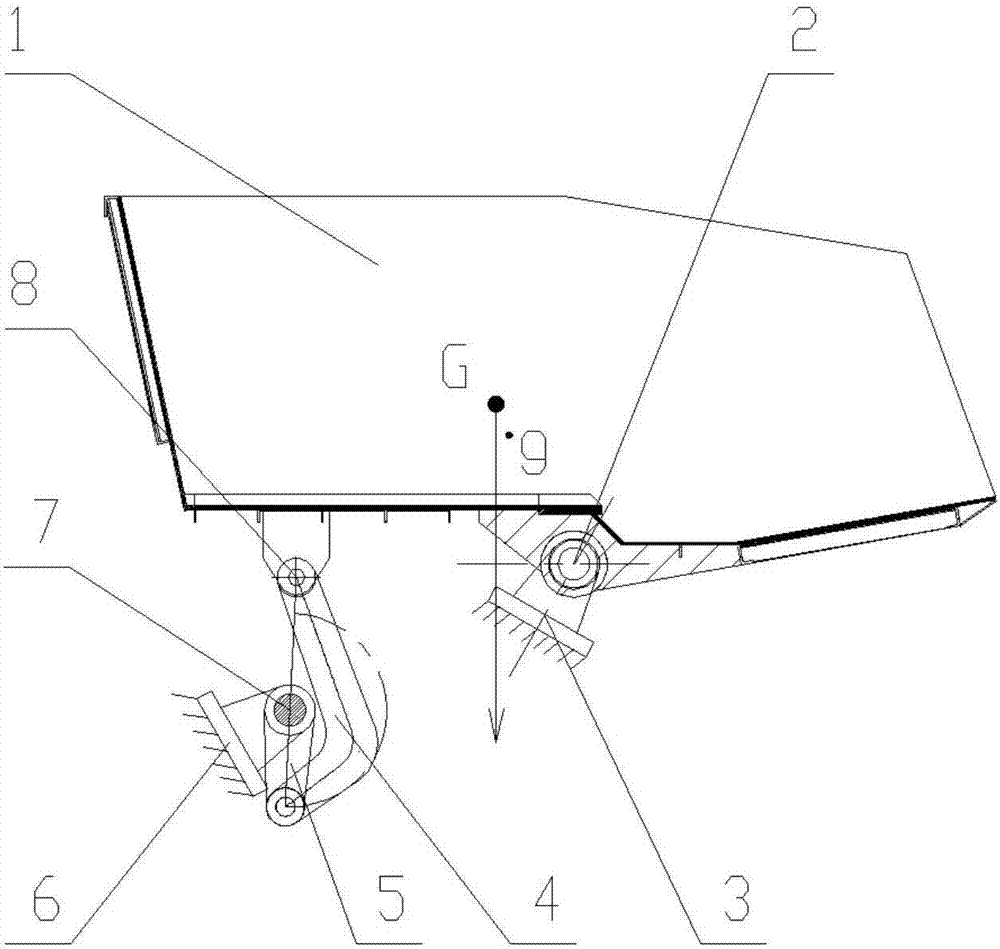
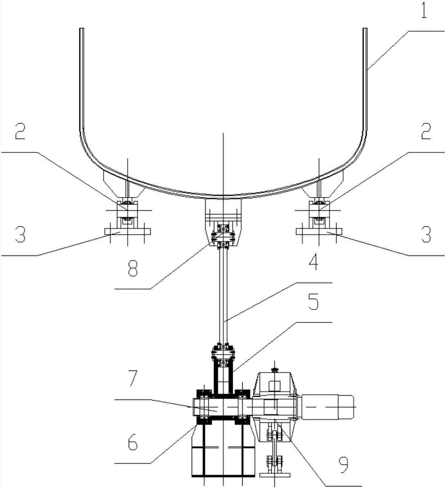
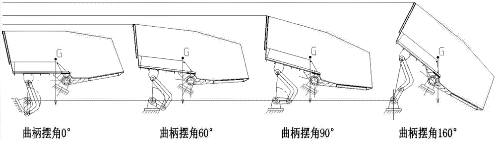
[0026] As shown in the figure, the tilting hopper in the present invention includes a hopper body 1 and a hopper slewing support 3, and also includes a tilting mechanism hinged at the rear of the hopper body 1. The tilting mechanism includes a connecting rod 4 and a crank 5, One end of the connecting rod 4 is hinged to the hopper body 1, the other end is hinged to one end of the crank 5, and the other end of the crank 5 is hinged to the crank rotary support 6 through the crank shaft 7; the center of gravity g of the hopper body 1 is located at the hopper rotary Between the hinge point 2 and the connecting rod support hinge point 8 and close to the hopper rotary hinge point 3, the hopper rotary hinge point 2 is the hinge point between the hopper body 1 and the hopper rotary support 3, and the connecting rod supports the hinge point 8 It is t...


PUM


Abstract

The invention discloses an overturning hopper. The overturning hopper comprises a hopper body, a hopper revolving support and an overturning mechanism, wherein the overturning mechanism comprises a link and a crank, one end of the link is hinged onto the hopper body, the other end of the link is hinged with the crank, and the other end of the crank is hinged onto a crank revolving support through a crank rotary shaft; and the receiving point and the unloading point of the hopper are both arranged at or close to the dead point of the overturning mechanism through optimizing the starting point and the ending point of the crank, so that the impacted force working condition of speed reducer equipment is optimized during the loading and the unloading of the overturning hopper. According to the mechanism, the centre-of-gravity position of the hopper body and the centre-of-gravity position of the hopper after the loading are further optimized, so that the centre of gravity of the hopper body is located between the revolving hinge point of the hopper and the supporting hinge point of the link and close to the revolving hinge point of the hopper; and requirements on the output torque of a speed reducer are greatly lowered by virtue of the force amplification effect of the link, so that the weight of the speed reducer equipment and the power of a tilting motor are greatly reduced, and the motor power and the energy consumption of the system are saved.

Description

technical field [0001] The invention belongs to the field of material transportation or handling, and in particular relates to a tipping hopper and a control method thereof. Background technique [0002] Tilting hopper is a common loading and unloading mechanical equipment, and its tilting mechanism determines the working quality of the tilting hopper to a large extent. [0003] There are many mechanical design methods to realize the charging and tipping functions of the tilting hopper, including cylinder hydraulic drive, electro-hydraulic push rod, electric push rod drive, direct drive of reducer, etc., each of which has advantages and disadvantages. For example, the electro-hydraulic push rod drive has the advantages of simple equipment and light weight, but the thrust is small and the reliability is slightly poor in use. The hydraulic drive of the oil cylinder needs to be equipped with a hydraulic system. The system (including various valves, motors, sensors, etc.) and c...

Claims


Application Information

Patent Timeline
Patent Type & Authority Applications(China)
IPC IPC(8): B65G65/23B65D88/28
CPCB65D88/28B65G65/23B60P1/12B60P1/283B65D88/56
Inventor 黄其明高瞻施维枝谈存真王永猛
Owner CISDI ENG CO LTD
Why Eureka
Try Eureka