Supersonic velocity detonation engine and propulsion system thereof

A propulsion system and supersonic technology, applied in the field of propulsion systems and supersonic detonation engines, can solve problems such as large aerodynamic resistance and aerodynamic heat, complex engine structure, large propulsion system volume, etc., and achieve the effect of improving combustion efficiency

Active Publication Date: 2017-07-07
NAT UNIV OF DEFENSE TECH
View PDF4 Cites 10 Cited by
  • Summary
  • Abstract
  • Description
  • Claims
  • Application Information

AI Technical Summary

Problems solved by technology

[0003] Under hypersonic conditions, the detonation combustor organizes combustion through the slope-induced detonation method. However, since the existing detonation-based engine considers the slope-induced detonation wave formation method to organize the detonation combustion, the oblique detonation wave directly Acting on the inner wall of the expanding nozzle, it interacts with the boundary layer on the wall of the expanding nozzle, causing the oblique detonation wave to propagate forward along the boundary layer, and the boundary layer has a greater influence on the oblique detonation wave. Detonation, resulting in greater aerodynamic drag and aerodynamic heat
[0004] At the same time, in the propulsion system in the prior art, the combustion chamber and the expansion nozzle are arranged separately. Since the combustion chamber needs to mix fuel, the length of the combustion chamber is generally long, resulting in a large volume of the entire propulsion system and a complicated structure of the engine.

Method used


Image

  • Supersonic velocity detonation engine and propulsion system thereof

Examples


Embodiment Construction

[0025] The core of the invention is to provide a propulsion system, which can significantly reduce the impact of the boundary layer on the oblique detonation wave, and at the same time ensure sufficient combustion of fuel. Another core of the present invention is to provide a supersonic detonation engine comprising the above propulsion system.

[0026] The following will clearly and completely describe the technical solutions in the embodiments of the present invention with reference to the accompanying drawings in the embodiments of the present invention. Obviously, the described embodiments are only some, not all, embodiments of the present invention. Based on the embodiments of the present invention, all other embodiments obtained by persons of ordinary skill in the art without making creative efforts belong to the protection scope of the present invention.

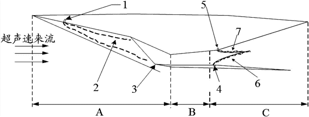
[0027] Please refer to figure 1 , figure 1 It is a structural schematic diagram of a specific embodiment of the pr...


PUM


Abstract

The invention discloses a propulsion system which comprises an air inlet channel, a combustion chamber and an expansion spraying pipe connected with the combustion chamber. A first hot jet flow spout allowing spraying of a hot jet flow is formed in the upper wall surface of the combustion chamber, a second hot jet flow spout allowing spraying of the hot jet flow is formed in the lower wall surface of the combustion chamber, after spraying the hot jet flows, the first hot jet flow spout and the second hot jet flow spout can induce a supersonic velocity incoming flow to form two strands of oblique detonation waves, and the two strands of oblique detonation waves can intersect in the middle of the expansion spraying pipe. According to the propulsion system provided by the invention, the first hot jet flow spout and the second hot jet flow spout are formed in the combustion chamber, the hot jet flows sprayed from the two hot jet flow spout induces the incoming flow to form the stable oblique detonation waves, and the oblique detonation waves produce regular reflection, so that the action of the detonation waves and a boundary layer is avoided, meanwhile, full combustion of incoming flow premixed gas is guaranteed, after combustion through the double oblique detonation waves, heat is released rapidly, expansion occurs to produce thrust, and the combustion efficiency is improved. The invention further discloses a supersonic velocity detonation engine comprising the propulsion system.

Description

technical field [0001] The invention relates to the field of detonation engine equipment, in particular to a propulsion system. In addition, the present invention also relates to a supersonic detonation engine comprising the above propulsion system. Background technique [0002] With the development of hypersonic vehicles, the efficiency of the propulsion system has become one of the bottlenecks restricting the further improvement of engine thrust, while the detonation combustion thermodynamic cycle has high efficiency and fast heat release, and the supersonic propulsion system based on detonation combustion has a compact layout and a simple structure , therefore, detonation-based engines can be used as a potential solution for hypersonic propulsion systems. [0003] Under hypersonic conditions, the detonation combustor organizes combustion through the slope-induced detonation method. However, since the existing detonation-based engine considers the slope-induced detonation...

Claims


Application Information

Patent Timeline
Patent Type & Authority Applications(China)
IPC IPC(8): F02K7/02F23R3/42F02C7/04F02C7/22
CPCF02C7/04F02C7/22F02K7/02F23R3/42
Inventor 陈伟强梁剑寒刘世杰林志勇蔡晓东孙健蒋露欣苗世坤
Owner NAT UNIV OF DEFENSE TECH
Why Eureka
Try Eureka