
Time detection method for increasing anti-interference capability of time difference type ultrasonic flowmeter

A time detection and ultrasonic technology, which is used in the measurement of flow/mass flow, liquid/fluid solid measurement, and measurement devices, etc., can solve problems such as timing errors and flow measurement errors, and improve measurement accuracy, ensure accuracy, and widen the range. the effect of

Inactive Publication Date: 2017-07-07
ZHEJIANG UNIV
View PDF3 Cites 8 Cited by
  • Summary
  • Abstract
  • Description
  • Claims
  • Application Information

AI Technical Summary

Problems solved by technology

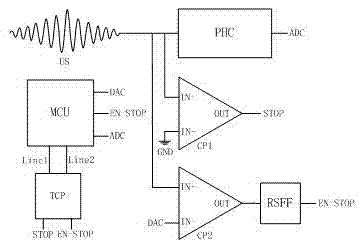
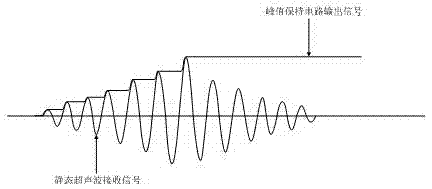
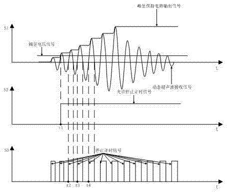
However, due to the existence of interference factors such as pressure, temperature, humidity, stains, and the components of the measured medium, the position of the peak sequence when the ultrasonic receiving signal reaches the threshold voltage for the first time is not the same. These interference factors will cause timing errors, resulting in flow measurement error

Method used


Image

  • Time detection method for increasing anti-interference capability of time difference type ultrasonic flowmeter
  • Time detection method for increasing anti-interference capability of time difference type ultrasonic flowmeter
  • Time detection method for increasing anti-interference capability of time difference type ultrasonic flowmeter

Examples


Embodiment

[0028] Requirements: (1) 7 consecutive pulse signals excite the ultrasonic sensor; (2) Use the fifth positive zero-crossing point of the ultrasonic received signal as the propagation time value of the ultrasonic received signal; (3) Calculate the peak in the position determination method of the received signal peak sequence When the sequence position is judged and marked, the obtained positive first dynamic peak amplitude is divided by the penultimate first dynamic peak amplitude; (4) the function f(DA m ,DA n ) is defined as

[0029] First, obtain the seven static peak amplitudes under static conditions. Table 1 shows the seven static peak amplitudes obtained under static conditions, the trigger attribution area determined by them, and the wave sequence for determining the threshold voltage for the first trigger, and the trigger attribution area The method is as follows: divide the obtained static peak amplitudes from small to large by the largest static peak amplitudes in...


PUM


Abstract

The invention discloses a time detection method for increasing the anti-interference capability of a time difference type ultrasonic flowmeter. The method comprises the following steps: receiving a determination method for signal peak sequence positions and obtaining information on supersonic wave peak position; utilizing a timing chip to obtain three and more time value of zero crossing points of ultrasonic receiving signals after receipt signals reach threshold voltage for the first time; utilizing a self-adaptive algorithm for propagation time value according to position information on wave peaks, selecting one of obtained time value of zero crossing points of ultrasonic receiving signals as propagation time value for ultrasonic receiving signals; achieving accurate measurement of propagation time value for ultrasonic receiving signals on the condition that interference factors change. The time detection method for increasing the anti-interference capability of the time difference type ultrasonic flowmeter has the following beneficial effects: the capability to resist the interference factors is increased; on the harsh working condition, accuracy of measurement for propagation time value for ultrasonic receiving signals is ensured; measurement precision is increased; and measurement upper limit and the ratio of measuring range are increased.

Description

technical field [0001] The invention relates to a time-difference ultrasonic flowmeter, in particular to a time detection method for improving the anti-interference ability of the time-difference ultrasonic flowmeter. Background technique [0002] With the continuous maturity of microelectronics technology and the continuous deepening of research in the ultrasonic field, ultrasonic flowmeters have been widely used in the field of flow measurement due to their excellent performance such as no pressure loss, wide range, and high precision. Among them, time difference ultrasonic flowmeters are the most widely used. . [0003] Transit-time ultrasonic flowmeter calculates fluid flow by measuring the forward and reverse propagation time difference of ultrasonic signals along the same path. In the transit-time ultrasonic flowmeter measurement technology, the detection of the propagation time value of the ultrasonic received signal is one of the most important technologies. Ultras...

Claims


Application Information

Patent Timeline
Patent Type & Authority Applications(China)
IPC IPC(8): G01F1/66
CPCG01F1/66
Inventor 傅新方泽华毛凯陈文昱肖继伟
Owner ZHEJIANG UNIV
Learn More