
Multi-flexible beam vibration control device and method based on synchronous belt drive
A flexible beam and synchronous belt technology, applied in the field of multi-flexible beam vibration control devices, can solve the problems of synchronous belt elastic control accuracy, influence on control accuracy, high installation requirements, etc., achieve small pre-tightening force, improve detection accuracy, and transmission efficiency high effect
- Summary
- Abstract
- Description
- Claims
- Application Information
AI Technical Summary
Problems solved by technology
Method used
Image

Examples
Embodiment
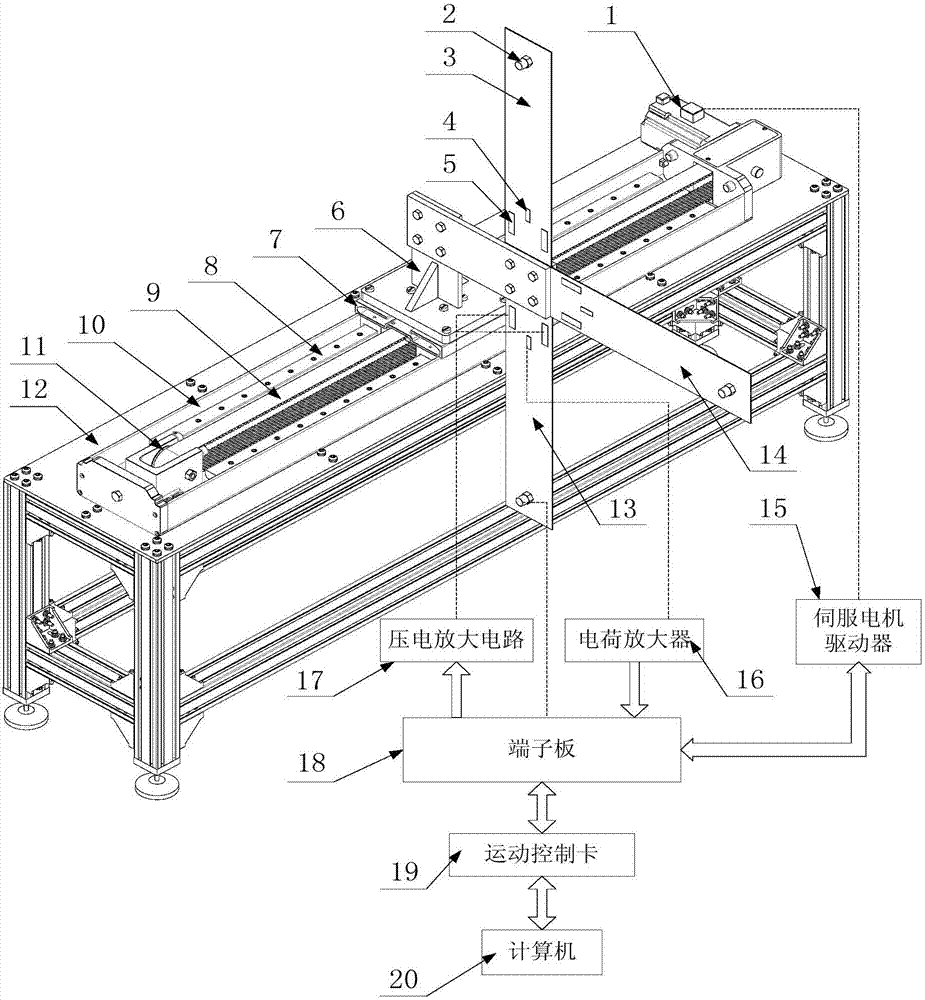
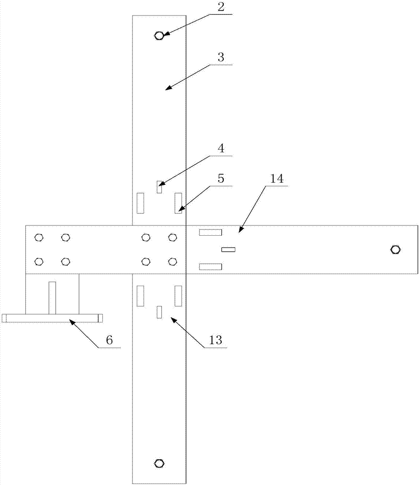
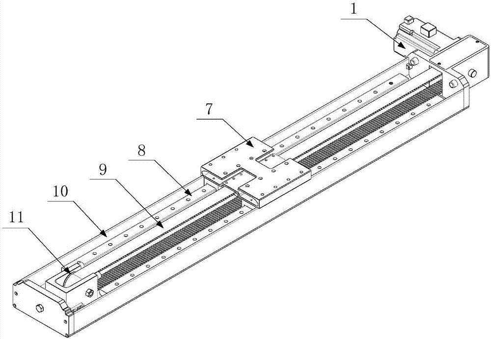
[0037] Such as Figure 1-Figure 6 As shown, a multi-flexible beam vibration control device driven by a synchronous belt includes a flexible beam body, a detection part and a control part;
[0038] The flexible beam body includes three flexible beams with exactly the same size, material and structure, which are respectively the first flexible beam 3, the second flexible beam 13 and the third flexible beam 14, and one end of the three flexible beams is fixed on a mechanical clamp. On the device 6, the other end is a free end, the first flexible beam is fixed vertically upward, the second flexible beam is fixed vertically downward, and the center points of the two flexible beams are on the same vertical line Above, the third flexible beam is fixed along the horizontal direction. In this embodiment, it is fixed horizontally to the right and is located in the middle of the first and second flexible beams. The flexible beam designed in this way has no vibration between the three. C...
PUM
 Abstract
Description
Claims
Application Information