A spinning machine or a twister with a spindle rail capable of performing lifting motion

A technology of lifting movement, twisting machine, applied in the field of spinning machine or twisting machine

Active Publication Date: 2017-07-11
SAURER GERMANY GMBH & CO KG
View PDF5 Cites 5 Cited by
  • Summary
  • Abstract
  • Description
  • Claims
  • Application Information

AI Technical Summary

Problems solved by technology

However, this spinning machine or twisting machine has a still complex str...

Method used


Image

  • A spinning machine or a twister with a spindle rail capable of performing lifting motion
  • A spinning machine or a twister with a spindle rail capable of performing lifting motion
  • A spinning machine or a twister with a spindle rail capable of performing lifting motion

Examples


Embodiment Construction

[0027] In the following description of the preferred embodiments of the present invention, the same or similar reference numerals are used for the parts shown in the various figures and having similar functions, and the repeated description of these parts is omitted here.

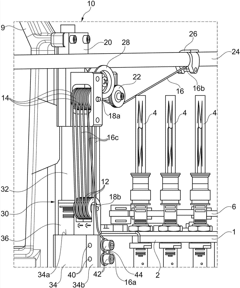
[0028] figure 1 A side perspective view of the pulley block mechanism 10 is shown, which is connected to the longitudinal left end 2 of the spindle rail 1 of a spinning or twisting machine according to one embodiment. The sheave block mechanism 10 is based on the sheave-pull principle and in this embodiment is constructed in the form of a multiplier block. The pulley block mechanism 10 includes four movable pulleys 12 and five fixed pulleys 14, each of which has a groove for guiding a wire rope 16 as a tie. The movable pulley 12 and the fixed pulley 14 are arranged along the same rotation axis 18a, 18b, respectively. The rotary shafts 18a, 18b are parallel to each other and located in the same plane. The...


PUM


Abstract

The invention relates to a spinning machine or a twister with a spindle rail capable of performing lifting motion. The spinning machine or twister comprises a support base and at least one spindle rail (1) which is held by the support base in a manner of capable of performing lifting motion along at least one guide mechanism (30). The spinning machine or twister is characterized in that the support base holds a pulley block mechanism (10) which comprises a tying belt (16) which is guided to pass by at least one moving wheel (12) and at least one fixed wheel (14) alternately, wherein the at least one moving wheel (12) is connected with the spindle rail (1) in a position-changeable manner, and the at least one fixed wheel (14) is connected with the support base in a position-fixed manner; when a first end (16a) of the tying belt is installed in a position-fixed manner, the numbers of the fixed wheels (14) and the moving wheels (12) which the tying belt pass by before reaching a position-changeable second tying belt end (16b) are the same, or when the first end (16a) of the tying belt (16) is fixed in a manner of being movable along with the spindle rail (1), the tying belt pass by more fixed wheels (14) than moving wheels (12) during extending.

Description

technical field [0001] The invention relates to a spinning or twisting machine having a support and at least one spindle rail held by the support so as to be movable up and down along at least one guide. Background technique [0002] In a spinning or twisting machine, the relative movement between the ring rail and the spindle rail required for spinning or twisting is carried out by means of a ring rail that can move up and down, which can move up and down, in combination with a fixed position spindle rails or vice versa. The liftable ring rail has the advantage of lower mass compared to the liftable ingot rail. For example, a ring strip designed for 24 spindles can have a mass that is 7 times less than the corresponding spindle rail. With the spindle rail that can move up and down, smaller yarn tension, smaller fluctuation range of yarn elasticity and higher productivity can be obtained. However, the structural design of the movable spindle rails has proven to be complic...

Claims


Application Information

Patent Timeline
IPC IPC(8): D01H7/14D01H1/241
CPCD01H1/20D01H7/10D01H1/241D01H7/14
Inventor 彼得·曼恩
Owner SAURER GERMANY GMBH & CO KG
Why Eureka
Try Eureka