Axial flow-centrifugation integral bladed disc type combined compression system

An integral blisk and combined compression technology, applied in gas turbine installations, machines/engines, mechanical equipment, etc., can solve the problems of rotor torque transmission and operation reliability reduction, increase of rotor system parts, engine design difficulties, etc. Vibration margin, improve reliability, widen the effect of operating envelope

Active Publication Date: 2017-07-11
中科航星科技股份有限公司
View PDF6 Cites 9 Cited by
  • Summary
  • Abstract
  • Description
  • Claims
  • Application Information

AI Technical Summary

Problems solved by technology

However, the increase of the axial flow compressor stage leads to a complex engine structure, especially the axial flow rotor impeller increases the rotor system parts, reduces the reliability of the rotor torque transmission and operation, and brings difficulties to the engine design

Method used


Image

  • Axial flow-centrifugation integral bladed disc type combined compression system
  • Axial flow-centrifugation integral bladed disc type combined compression system

Examples


Embodiment Construction

[0019] In order to make the object, technical solution and advantages of the present invention clearer, the present invention will be further described in detail below with reference to the accompanying drawings and examples.

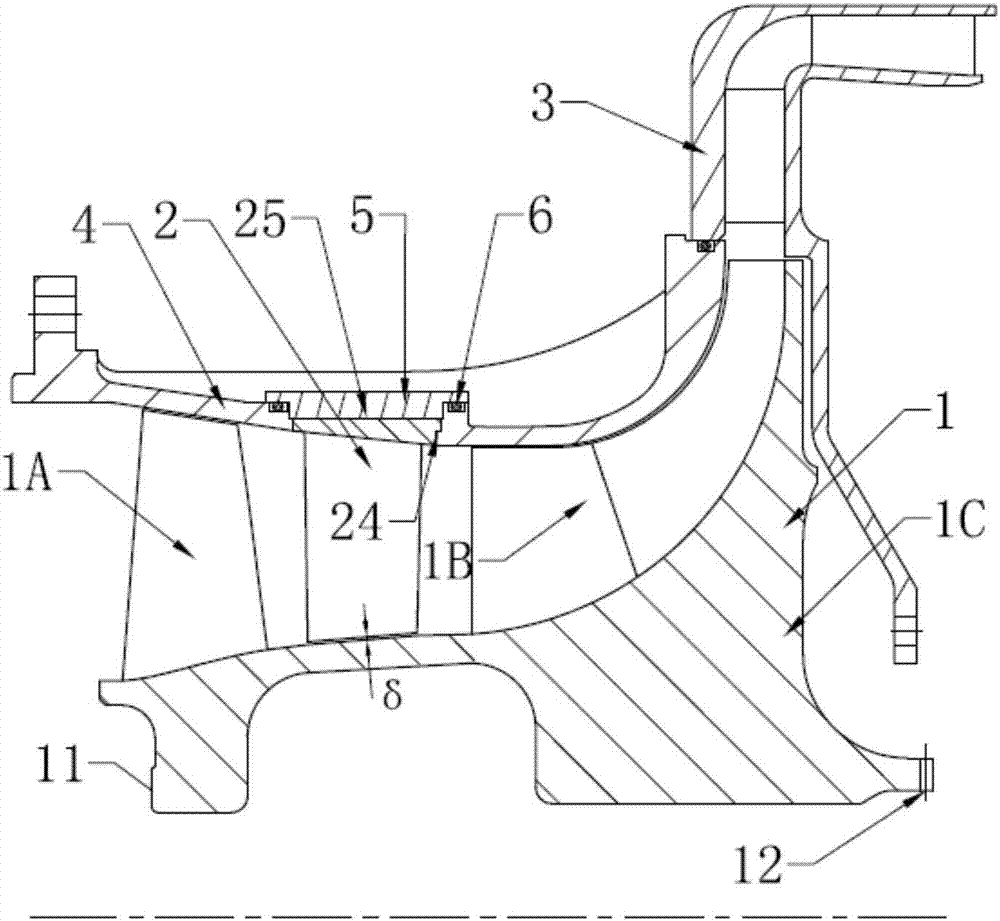
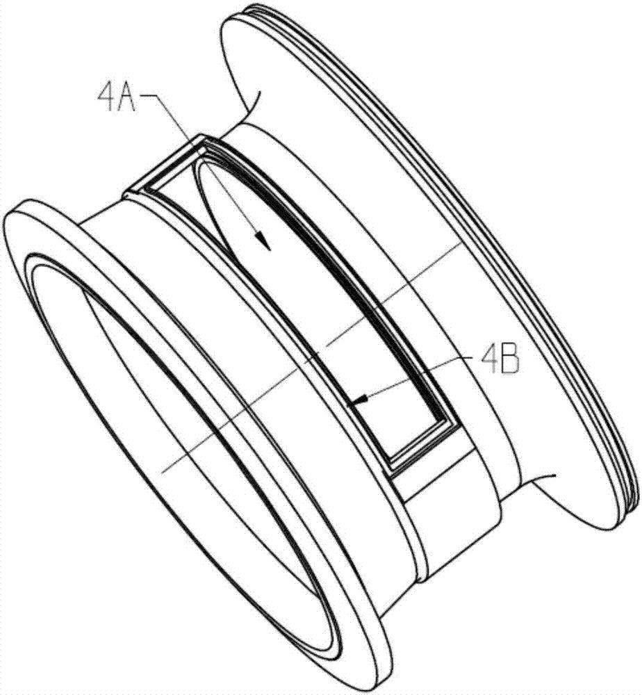
[0020] Such as figure 1 , 2 As shown, the axial flow-centrifugal integrated blisk type combined compression system of the present invention includes a first-stage axial flow compressor, a first-stage centrifugal compressor and a stator casing. The axial compressor includes an axial rotor and an axial stator 2 , and the centrifugal compressor includes a centrifugal impeller and a radial-axial diffuser 3 . Among them, the axial flow rotor is arranged upstream of the axial flow stator 2, the centrifugal impeller is arranged downstream of the axial flow stator 2, the axial flow stator is located between the axial flow rotor and the centrifugal impeller, and the radial-axial diffuser 3 is arranged in the centrifugal downstream of the impeller. The axial f...


PUM


Abstract

The invention discloses an axial flow-centrifugation integral bladed disc type combined compression system. An axial flow impeller and a centrifugal impeller are integrally connected to form an integral bladed disc; an axial flow stator is arranged between an axial flow rotor and the centrifugal impeller; an impeller outer ring of an axial flow gas compressor and an impeller outer ring of a centrifugal gas compressor are integrally connected to form an integral impeller outer ring; one assembling reserving cavity for assembling stator outer rings is formed in the integral impeller outer ring; the axial flow stator is divided into a plurality of equal parts in the circumferential direction; the stator outer rings equally divided are mounted in the assembling reserving cavity; the stator outer rings are limited in the radial direction through a cylindrical surface at the top of the assembling reserving cavity; and the stator outer rings are compressed through compression rings. The axial flow-centrifugation integral bladed disc type combined compression system simplifies the structure to improve the reliability of an engine and reduce the production cost; a cantilever stator is adopted to increase the surge margin of an axial flow gas compressor stage so as to further increase the surge margin of the combined compression system and expand the operational covered wire of the engine.

Description

technical field [0001] The invention relates to an axial flow-centrifugal impeller integral blisk structure, a cantilever stator adapted to the structure and an axial flow-centrifugal combined compression system. Specifically, it relates to an axial flow-centrifugal combined compression system with compact structure, high efficiency, large margin and high reliability, which is applied to a small gas turbine engine. Background technique [0002] Small gas turbine engines mostly use axial-centrifugal combined compressors, single-stage centrifugal compressors or two-stage centrifugal compressors as their compression systems. Centrifugal compressors are widely used due to their simple structure and high single-stage pressure ratio, but their inherent low efficiency and limited single-stage pressure ratio are particularly prominent, which is a very obvious defect for engines with high economic requirements . [0003] Axial-centrifugal combined compressor is the first choice for...

Claims


Application Information

Patent Timeline
Patent Type & Authority Applications(China)
IPC IPC(8): F02C3/08
CPCF02C3/08
Inventor 阳诚武赵胜丰韩戈张燕峰卢新根李紫良
Owner 中科航星科技股份有限公司
Why Eureka
Try Eureka