Bearing installation machine

A technology for mounting machines and bearings, applied in metal processing, metal processing equipment, manufacturing tools, etc., can solve problems such as flatness deviation, installation error, axis deviation, etc. Effect

Active Publication Date: 2017-07-14
KUNMING UNIV OF SCI & TECH
View PDF6 Cites 4 Cited by
  • Summary
  • Abstract
  • Description
  • Claims
  • Application Information

AI Technical Summary

Problems solved by technology

[0003] The technical problem to be solved by the present invention is: the present invention provides a bearing installation machine to solve the problems of installation errors caused by installation, such as axis deviation, flatness deviation, etc.

Method used


Image

  • Bearing installation machine
  • Bearing installation machine
  • Bearing installation machine

Examples


Embodiment 1

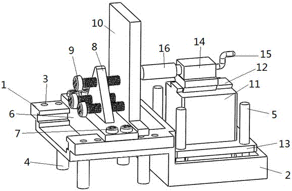
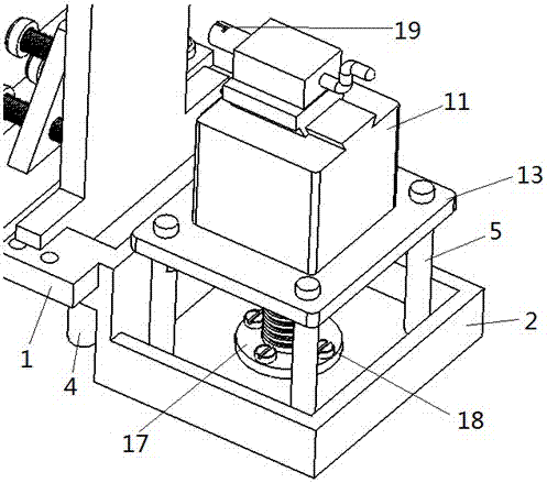
[0026] Embodiment 1: as Figure 1-9 As shown, a bearing installation machine includes a chute seat 1, a support seat 2, a fixed plate 6, a tripod 8, a baffle plate 10, a supporting base 11, a lifting platform 13, a hydraulic slider 14, a top block 16, and a screw 17 , electric nut column 26, bearing 27; described chute seat 1, support seat 2 are integral structure, chute seat 1 is higher than support seat 2, and described chute seat 1 is supported by support column 4, and on chute seat 1 There is a bow-shaped slideway, and the bottom of the fixed plate 6 is installed on the chute seat 1 with the bow-shaped slideway, and fixed on the hole Ⅰ3 of the chute seat 1 with the screw Ⅰ7; the tripod 8 is installed on the fixed plate 6, and the tripod 8 passes through the screw Ⅱ9 passes through the threaded hole on it and is installed on the tripod 8; the bottom of the baffle plate 10 cooperates with the bow-shaped slideway and is installed on the chute seat 1; the upper bottom surface ...

Embodiment 2

[0027] Embodiment 2: as Figure 1-9 As shown, a bearing installation machine, embodiment 2 is the same as embodiment 1, wherein, the jacking block 16 is respectively a bearing plug 29 and a positioning plug 30 according to different heads.

[0028] There are several holes I3 on ​​both sides of the chute seat 1, arranged according to a certain distance.

[0029] The bearing plug 29 is a stepped head, and the stepped portion is a transition curve.

Embodiment 3

[0030] Embodiment 3: as Figure 1-9 As shown, a bearing installation machine, embodiment 3 is the same as embodiment 1, wherein, the jacking block 16 is respectively a bearing plug 29 and a positioning plug 30 according to different heads. There are several holes I3 on ​​both sides of the chute seat 1, arranged according to a certain distance. The bearing plug 29 is a stepped head, and the stepped portion is a transition curve. The positioning plug 30 is a spherical surface.

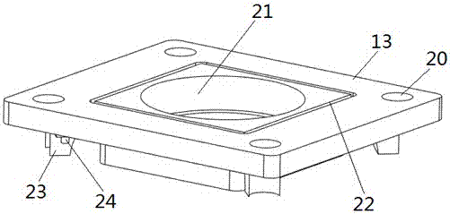
[0031] When in use, according to the size of the bearing and the distance from the center of the bearing hole to the bottom surface, firstly adjust the height of the lifting table 13 accurately through the laser range finder 24 and the electric nut column 26, and then place the bearing seat to be installed on the chute seat 1 , adjust the position of the fixed plate 6 and the baffle plate 10 according to the width of the bearing seat, and pre-tighten the screw Ⅱ9, then install the top block 16b (the to...


PUM


Abstract

The invention relates to a bearing installation machine and belongs to the technical field of mechanical tools. The bearing installation machine comprises a sliding groove seat, a supporting seat, a fixing plate, a triangular rack, a baffle, a supporting stand, a lifting table, a hydraulic sliding block, an abutting block, a lead screw, an electric nut post and a bearing. According to the size of the bearing and the distance between the center of a bearing hole of the bearing and the bottom face, the height of the lifting table is accurately adjusted through a laser ranging device and the electric nut post firstly. According to the bearing installation machine, the overall structure is simple, the center position of the bearing can be well located through an arc-shaped abutting head of the abutting block and the laser ranging device, the bearing can be stably placed on a bearing seat through the bearing abutting head, and the installation precision is guaranteed; a lifting device is suitable for bearing seats of various sizes, and adjustment is accurate and convenient; and the whole structure is convenient to assemble and disassemble and easy to manufacture.

Description

technical field [0001] The invention relates to a bearing installation machine, which belongs to the technical field of mechanical tools. Background technique [0002] Bearings play an extremely important role in mechanical transmission, which guarantees the stability and high efficiency of transmission, but its installation requires certain precision requirements. Manual or some simple tool installation will cause installation errors, such as axis Deviation, flatness deviation, etc. These problems will cause transmission errors, reduce mechanical life, reduce stability, reduce efficiency, and even get stuck. Now the bearing installation tools on the market have solved this problem to a certain extent, but there are still some shortcomings. , so in order to better solve these problems, it is necessary to improve the bearing installation tool so that it can better guarantee the above requirements. Contents of the invention [0003] The technical problem to be solved by the...

Claims


Application Information

Patent Timeline
Patent Type & Authority Applications(China)
IPC IPC(8): B23P19/027
CPCB23P19/027
Inventor 张印辉张越何自芬武玉琪
Owner KUNMING UNIV OF SCI & TECH
Why Eureka
Try Eureka