Modular circuit, LED lamp and module lamp

A modular, LED light source technology, applied in the field of lighting, can solve the problems of being unsuitable for small batch and multi-variety customized production, PCB hard board can not be bent arbitrarily, and the thermal resistance of the insulation layer of the circuit board is large, etc., to guide green consumption, The effect of promoting industry development and improving adaptability

Active Publication Date: 2017-07-14
HUNAN YUEGANG MOOKRAY IND CO LTD
View PDF10 Cites 9 Cited by
  • Summary
  • Abstract
  • Description
  • Claims
  • Application Information

AI Technical Summary

Problems solved by technology

[0004] However, as lighting products, including many personalized customized products in other industries, this circuit design method has many disadvantages. For example, in terms of cost control, the product must have a certain scale to facilitate production by PCB welding technology Customized production of small batches and multiple varieties; in terms of heat conduction, the insulation layer of the circuit board has a large thermal resistance, which is not conducive to heat dissipation; in terms of shape and structure, PCB hard boards cannot be bent arbitrarily, and soft boards cannot be shaped arbitrarily; in terms of waterproof performance , the peripheral sealing process must be added twice, etc.
These problems have brought many adverse effects on the research and development, design, manufacture, installation, use and maintenance of lighting products, hindering the healthy development of the product industry.

Method used


Image

  • Modular circuit, LED lamp and module lamp
  • Modular circuit, LED lamp and module lamp
  • Modular circuit, LED lamp and module lamp

Examples


Embodiment 1

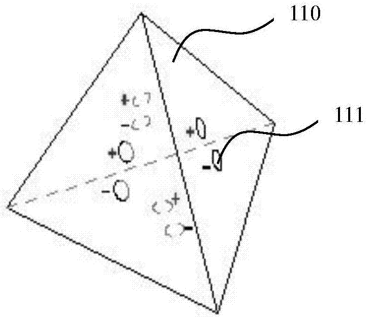
[0052] like Figures 1 to 14 As shown, a modular circuit includes a female plug module 100 and a female plug connector 200 connected to the female plug module 100 .

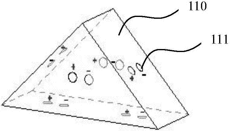
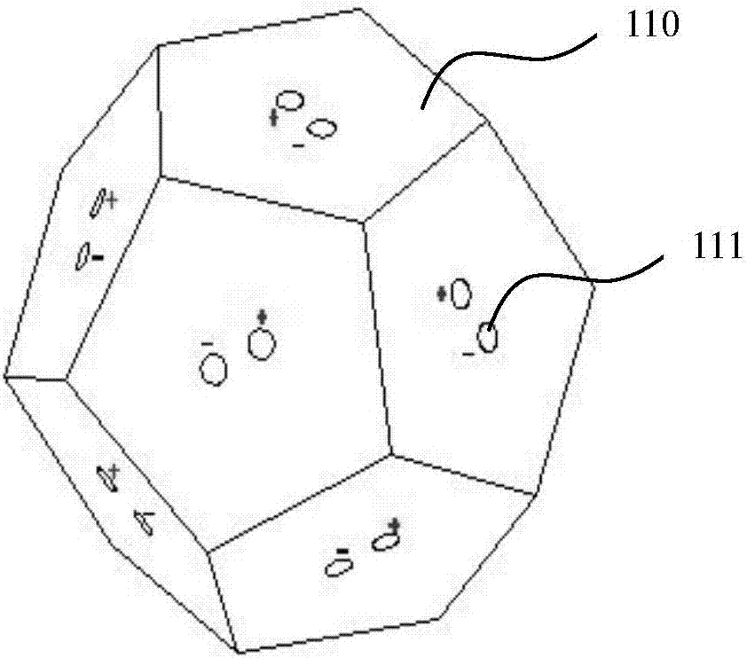
[0053] The female plug module 100 includes an N-hedron 110 , where N is greater than or equal to two. The female plug module 100 can be as figure 1 The tetrahedron shown, figure 2 The pentahedron shown, image 3 The 12-hedron shown, Figure 4 The decahedron shown or Figure 5 The irregular polyhedron shown and so on.

[0054] A plurality of first insertion holes or first pins 111 are provided on each surface of the N-hedron 110 to form a plurality of positive and negative connection points. The first jacks or first pins 111 on different surfaces are conductively connected in series or in parallel, so that multiple circuits in series or in parallel are formed on the N-hedron 110 . The LED light source 300 can be plugged into the female plug module 100, such as Image 6 shown.

[0055] The female plug co...

Embodiment 2

[0064] like Figure 15 , Figure 16 As shown, this embodiment provides an LED lamp, which includes a female plug module 100 , a plurality of plug-in LED light sources 300 , a lamp holder 400 and a plug-in power module 500 .

[0065] The plug-in power module 500 is disposed in the lamp base 400 , and the pins 510 on the plug-in power module 500 pass through the lamp base 400 to connect with the female plug-in module 100 .

[0066] A plurality of plug-in LED light sources 300 are plugged into the female plug-in module 100 as required, so that the LED lamp can be formed into a desired shape.

[0067] Plug-in power module 500 such as Figure 25 , Figure 26 , Figure 27 shown. It includes a radiator 301 ; a heat dissipation structure is formed at the bottom of the radiator 301 , a cup cavity 302 is provided at the top middle of the radiator 301 , and a first thread 311 is provided at the top edge of the radiator 301 .

[0068] Positive and negative electrodes 310 are arrange...

Embodiment 3

[0075] like Figure 17 to Figure 25 As shown, this embodiment provides a modular lamp, which includes a modular circuit and a pluggable LED light source 300 disposed on the modular circuit.

[0076] In the modular circuit, multiple female plug connectors 200 and multiple female plug modules 100 are combined and connected in different ways, so that the modular lamp can be formed into different shapes.

[0077] For example, the plug-in LED light source 300, the female plug module 100 and the freely bendable female plug connector 200 can be combined to form a Figure 17 Modular light fixture shown. The modular lamp is then connected with the power module 500 to form a completed lamp.

[0078] For example, the female plug module 100, the flat female plug connector 200 and the plug-in LED light source 300 can also be combined to form a Figure 18 Flat modular luminaire shown. The modular lamp is then connected with the power module 500 to form a completed lamp.

[0079] exist ...


PUM


Abstract

The invention relates to a modular circuit, an LED lamp and a modular lamp. The modular circuit comprises female insertion modules, and female insertion connecting pieces connected with the female insertion modules; the female insertion modules comprise N-surface bodies; multiple first insertion holes or first insertion pins are arranged on each surface of the N-surface bodies to form multiple positive and negative pole connecting points; the first insertion holes or the first insertion pins on the different surfaces are conductively connected in a serial connecting or parallel connecting manner to form multiple serial-connected or parallel-connected circuits on the N-surface bodies, wherein N is greater than and equal to 2; the female insertion connecting pieces comprise connecting piece bodies; second insertion holes or second insertion pins are respectively arranged at two ends of the connecting piece bodies; the second insertion holes of the second insertion pins at two ends of the connecting piece bodies are conductively connected in a serial connecting or parallel connecting manner to form multiple serial-connected or parallel-connected circuits on the connecting piece bodies; and multiple female insertion connecting pieces and multiple female insertion modules are combined and connected according to different modes to form serial-connected, parallel-connected or serial / parallel-connected circuits.

Description

technical field [0001] The invention relates to the technical field of lighting, in particular to a modular circuit, an LED lamp and a modular lamp. Background technique [0002] Throughout the 20-year development history of the LED industry, we can see that the circuit connection methods of all LED products are connected through PCB circuit boards, flexible FCC circuit boards, wires and plugs. Voltage, current and data transmission are all controlled through circuit board layout design. Wherein, the LED is welded on the circuit board. Connectors are only used for current and data conduction between wires and boards, depending on the existence of circuit boards and wires. It cannot become a circuit control device independently. [0003] In addition, in the past 20 years of development of the LED industry, no matter what kind of product, its connection method is inseparable from circuit boards, wires and connectors. This circuit connection method is also the basic mode fo...

Claims


Application Information

Patent Timeline
IPC IPC(8): F21V23/06F21V23/00F21V19/00F21Y115/10
CPCF21V19/003F21V23/003F21V23/06F21S2/005F21V29/503F21V29/70F21Y2105/18F21Y2103/10F21Y2115/10F21V7/26F21V7/05F21V13/14F21V17/12F21V19/0025F21V23/02H01R29/00
Inventor 朱衡
Owner HUNAN YUEGANG MOOKRAY IND CO LTD
Why Eureka
Try Eureka