
Impact-shaped composite spherical energy-dissipating structure for vertical hole blasting

A spherical, energy-dissipating seat technology, which is applied in blasting and other directions, can solve problems such as low construction efficiency, collision and friction of hole walls, and non-smooth hole walls, and achieve the effects of easy operation, improved safety, and good stress wave emission effect

Active Publication Date: 2018-08-10
WUHAN UNIV
View PDF5 Cites 0 Cited by
  • Summary
  • Abstract
  • Description
  • Claims
  • Application Information

AI Technical Summary

Problems solved by technology

However, the existing energy-dissipating-energy-gathering structure is in the shape of a cone or an oblique circular frustum. Due to the influence of existing construction conditions, the hole wall formed by drilling is not smooth. When the energy-dissipating-energy-gathering structure is placed from the top to the bottom of the hole , it will inevitably collide with the hole wall and cause the hole to be stuck, and the construction efficiency is extremely low
In addition, after the installation is completed, most of the conical structures are not level, causing some explosion stress waves to reflect downward, which in turn increases the damage to the bottom of the hole

Method used


Image

  • Impact-shaped composite spherical energy-dissipating structure for vertical hole blasting
  • Impact-shaped composite spherical energy-dissipating structure for vertical hole blasting
  • Impact-shaped composite spherical energy-dissipating structure for vertical hole blasting

Examples


example 1

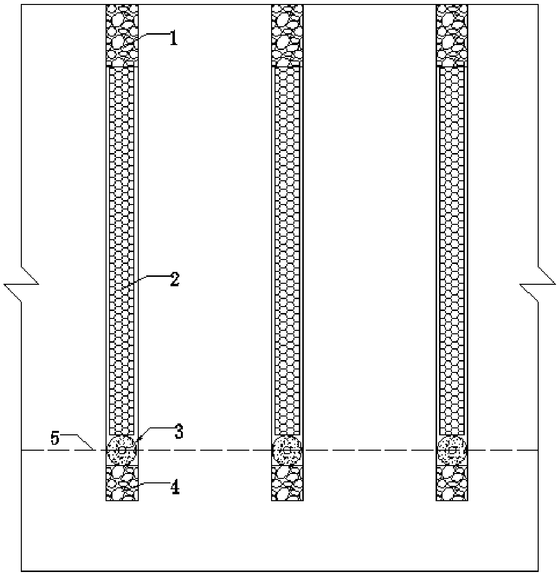
[0044] The rock foundation blasting excavation project of a water conservancy and hydropower project needs to improve the flatness of the foundation surface. Adopt deep hole step blasting, vertical blast hole, drilling diameter is Φ 炮孔 =90mm, the rock base is horizontal, the drilling depth is 10m, of which the over-depth is 0.3m, the plugging length is 2m, the hole spacing is 2.0-2.5m, and the hole bottom initiation method is adopted.

[0045] Using the "outside soft inside hard" type hole bottom energy dissipation structure of the present invention, the specific implementation steps are as follows:

[0046] Step 1: Prefabricated energy dissipation structure,

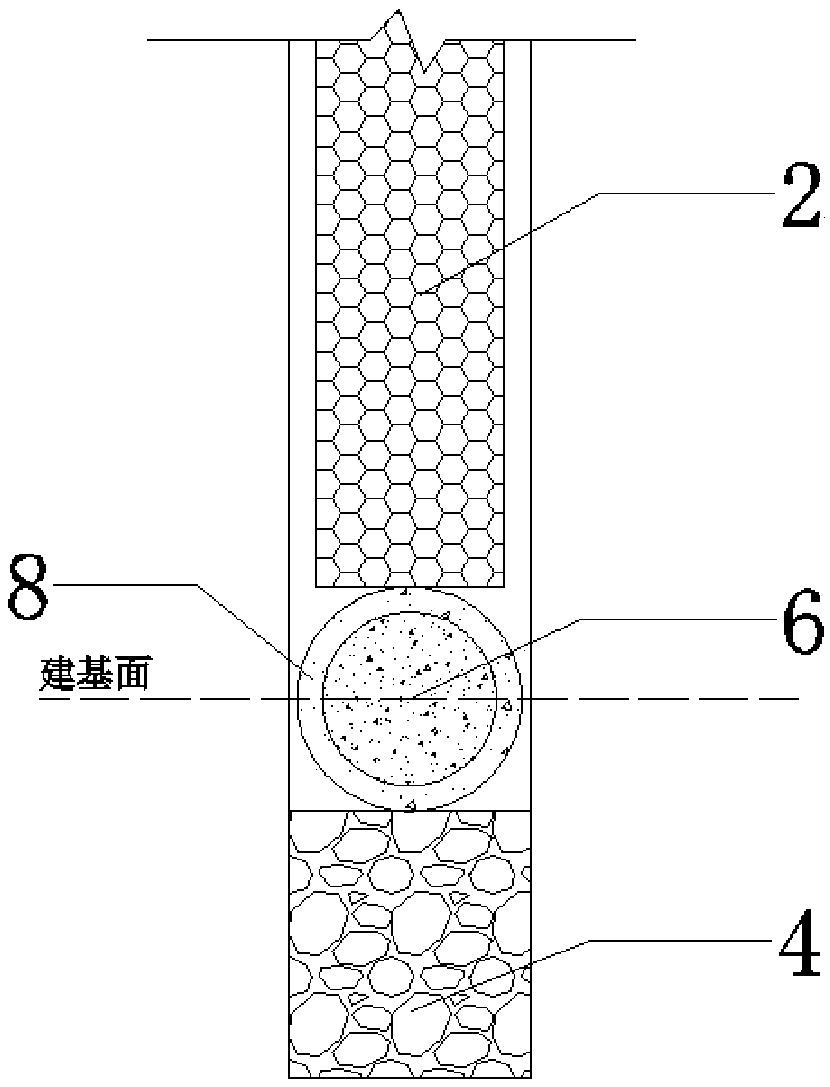
[0047] According to the diameter of the designed blast hole, the energy dissipation structure is prefabricated, and the shape of the structure is as follows image 3 , 5 As shown, size requirements:

[0048] Φ 内 =70mm, Φ 外 =84mm.

[0049] According to the material conditions of cement, water, iron sand and high-e...

example 2

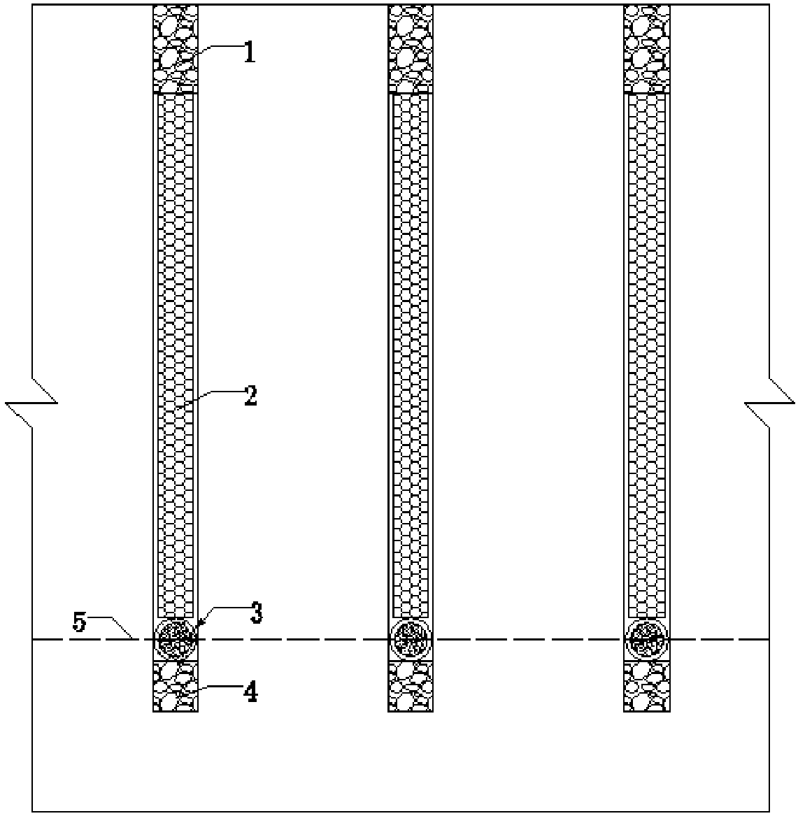
[0060] The rock foundation blasting excavation project of a water conservancy and hydropower project needs to improve the flatness of the foundation surface. Adopt deep hole step blasting, vertical blast hole, drilling diameter is Φ 炮孔 =90mm, the rock base is horizontal, the drilling depth is 10m, of which the over-depth is 0.3m, the plugging length is 2m, the hole spacing is 2.0-2.5m, and the hole bottom detonation method is adopted.

[0061] The specific implementation steps of the “outer hard inner soft” type hole bottom energy dissipation structure of the present invention are as follows:

[0062] Step 1: Prefabricated energy dissipation structure,

[0063] According to the diameter of the designed blast hole, the energy dissipation structure is prefabricated, and the shape of the structure is as follows Figure 4 , 6 As shown, size requirements:

[0064] Φ 内 =15mm, Φ 外 =84mm.

[0065] According to the material conditions of cement, water, iron sand and high-efficie...


PUM


Abstract

The invention provides an impacting-shaping composite spherical energy dissipation structure for vertical hole blasting. The energy dissipation structure comprises a composite spherical energy dissipation base and a buffer layer located below the composite spherical energy dissipation base, wherein the composite spherical energy dissipation base is of a double-layer structure which is soft externally and hard internally or hard externally and soft internally from outside to inside. According to the energy dissipation structure, under the action of an initial impact load after explosive detonation in a blast hole, the composite spherical energy dissipation base generates secondary plasticity, finally an ellipsoidal or a concave-shaped rigid cushion block reflects most of the explosion energy which is propagated in the rock mass below the hole bottom, meanwhile, the composite spherical energy dissipation base and the buffer layer absorb partial explosion energy in the deformation process, and therefore the rock on the foundation surface can be broken, the rock on the hole bottom can be protected, and the existing horizontal pre-cracking or smooth blasting technology can be partially replaced. The energy dissipation structure is simple and convenient to install, can partially replace the existing horizontal pre-cracking or smooth blasting technology and is suitable for protecting layer rock mass blasting excavation in the fields of water conservancy and hydropower, nuclear power, traffic and the like.

Description

technical field [0001] The invention relates to an impact-shaped composite spherical energy-dissipating structure for vertical hole blasting, which is suitable for blasting excavation of protective layer rock mass in the fields of water conservancy and hydropower, nuclear power, transportation and the like. Background technique [0002] Rock foundation is the foundation of engineering buildings, and its excavation quality directly affects the stability and safety of buildings above it. During the blasting and excavation of rock mass, due to the effect of blast load, dynamic damage to the retained rock mass will inevitably occur while the rock blasting is completed, and its construction quality is closely related to the excavation quality of the rock base. Therefore, there is an urgent need to improve the conventional blasting to efficiently complete the excavation of the rock foundation while ensuring the quality. In order to reduce the impact of blasting on the bedrock, th...

Claims


Application Information

Patent Timeline
Patent Type & Authority Patents(China)
IPC IPC(8): F42D5/045F42D1/08F42D3/04
CPCF42D1/08F42D3/04F42D5/045
Inventor 严鹏叶飞卢文波陈明王高辉
Owner WUHAN UNIV
Learn More