
Wavelet iterative estimation based finite difference contrast source full waveform inversion method

A full-waveform inversion, finite difference technology, applied in measurement devices, instruments, scientific instruments, etc., can solve the problems of large amount of calculation, lack of inversion, deviation of inversion results from the real model, etc. Effect

Inactive Publication Date: 2017-07-14
CHINA UNIV OF PETROLEUM (EAST CHINA)
View PDF14 Cites 6 Cited by
  • Summary
  • Abstract
  • Description
  • Claims
  • Application Information

AI Technical Summary

Problems solved by technology

The main calculation amount of full waveform inversion in the frequency domain lies in a large number of forward modeling simulations, which need to solve a huge linear equation system. Because the direct method (such as LU decomposition) has the advantage of calculating multiple shots, it has been widely used. Its main The amount of calculation is the decomposition operation of the matrix, and the amount of calculation is relatively large
At the same time, due to the lack of accurate source wavelet information, when the difference between the simulated wavelet and the real wavelet is too large, the inversion results will completely deviate from the real model

Method used


Image

  • Wavelet iterative estimation based finite difference contrast source full waveform inversion method
  • Wavelet iterative estimation based finite difference contrast source full waveform inversion method
  • Wavelet iterative estimation based finite difference contrast source full waveform inversion method

Examples


Embodiment 2

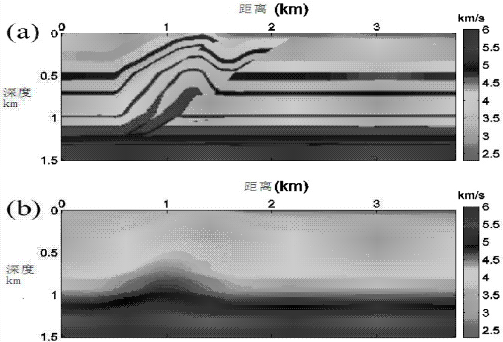
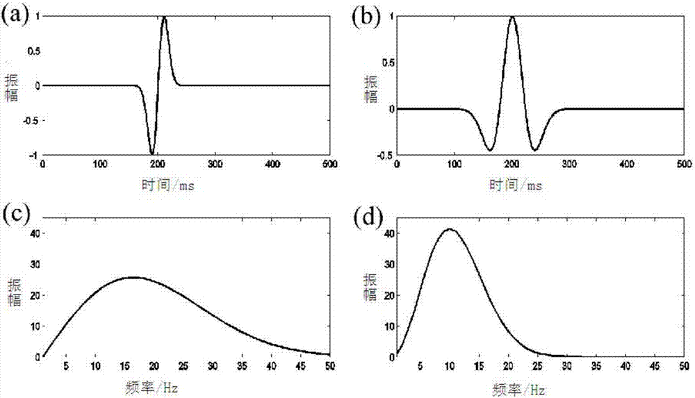
[0088] As another embodiment of the present invention, the inventor applies the scheme of the present invention to an overthrust model (i.e. a pushover model), such as Figure 12 As shown, the method of the present invention has been further verified, and the initial smooth velocity model (such as figure 2 b) It is smoothed by the overthrust model, and the first derivative of the Gaussian function is used as the real wavelet ( image 3 a) for generating the observed wavefield, image 3 c is its corresponding amplitude spectrum. In the inversion, the simulated wavelet that generates the background wave field is the Reich wavelet with a main frequency of 10 Hz ( image 3 b), from its amplitude spectrum ( image 3d) It can be seen that the frequency band of the real wavelet is significantly wider than that of the simulated wavelet, and the amplitude difference between the two is large. The comparison source inversion method is different from the conventional full waveform inv...


PUM


Abstract

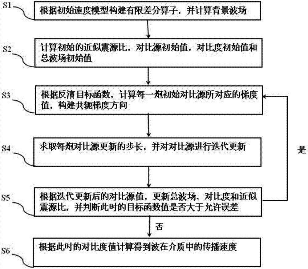
The invention discloses a wavelet iterative estimation based finite difference contrast source full waveform inversion method. The method comprises the steps of S1, inputting an initial velocity model, constructing a finite difference operator and calculating a background wave field; S2, calculating an approximate seismic focus ratio, calculating a scattering field thereby, and acquiring a contrast source initial value, a contrast initial value and a total wave field initial value; S3, calculating a gradient value corresponding to the initial contrast source at each shot, and constructing a conjugate gradient direction; S4, solving the update step length of the contrast source at each shot, and performing iterative update on the contrast source; S5, judging the size of an objective function value and an allowable error at the moment so as to decide whether iteration stops or not; and S6, calculating the propagation velocity of waves in a medium according to the current contrast value. The method disclosed by the invention effectively overcomes a problem that a result acquired by inversion seriously deviates from a real model when the difference between applied wavelets and actual wavelets is great, and the calculation amount is significantly reduced.

Description

technical field [0001] The invention relates to a finite difference contrast source full waveform inversion method based on wavelet iterative estimation, and belongs to the technical field of frequency domain acoustic wave full waveform inversion. Background technique [0002] Full waveform inversion (FWI) extracts velocity parameters based on the dynamic characteristics of seismic data, which is expected to obtain more accurate subsurface velocity structures compared with methods based on data kinematic characteristics such as travel time tomography. At present, from the perspective of implementation methods, it is mainly divided into two categories, time domain and frequency domain. Among them, in the frequency domain, only a few frequencies are needed to obtain high-precision inversion results, and it is easy to realize multi-scale calculations and has been rapidly popularized. The main calculation amount of full waveform inversion in the frequency domain lies in a large...

Claims


Application Information

Patent Timeline
Patent Type & Authority Applications(China)
IPC IPC(8): G01V1/28
CPCG01V1/282
Inventor 解飞黄建平
Owner CHINA UNIV OF PETROLEUM (EAST CHINA)
Learn More